This small and Simple LED Tester Circuit is like a small doctor for LED.
It helps to see if our light LED is working or not.
Think like a small setup one battery, some small resistor like tiny traffic light for electric and clip to put LED.
When we put LED in circuit check if LED lights or not.
If it lights then LED is good and healthy.
Circuit Working:
Parts List:
| Component Type | Description | Quantity |
|---|---|---|
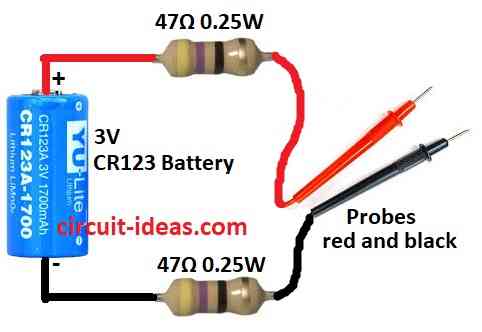
| Resistors | 47Ω 0.25W | 2 |
| Semiconductors | Battery CR123 3V | 1 |
| Probes red and black | 1 |
In this article multimeter with Vf function is not so good for green, blue or white LEDs as they just light very dim.
This small tester is very helpful especially for SMD LEDs.
They are easy to put wrong way so tester help check before soldering.
We can also use this to check many LEDs one by one to be sure all are put correct.
3V battery is enough to turn ON any LED but still safe not too much for reverse voltage.
Short circuit current is around 30mA which is not too much just enough.
To build the tester just solder two 47 ohm ¼ watt resistors to battery ends and then cover wires with teflon tube to stop short.
If teflon is not used then use normal plastic wire insulation which is also okay.
Make small bend kink near wire end to keep tube from sliding off.
Leads do not break easily but after many times bending they can cut.
But fixing is easy and just do not bend it too hard.
Battery is 3V lithium type taken from old circuit board.
Good battery show little more than 3V.
Other options: CR123 or DL123 camera battery.
Or just tape two 1.5V AA or AAA batteries together and connect them in series.
Formulas and Calculations:
This circuit is only for checking CR123A battery voltage.
Battery voltage is made lower by two 47 ohm resistors so multimeter probes stay safe.
To know voltage drop across each resistor then use this formula:
V = I * R
where:
- V is voltage drop in volts
- I is current in amps A
- R is resistor value in ohms Ω
So in this circuit:
V = 0.025A * 47Ω = 1.175V
That means both resistors together drop:
1.175V + 1.175V = 2.35V
So when multimeter probes touch the circuit it will show:
3V – 2.35V = 0.65V
To find how much resistor needed to limit current for LED then we need to use this formula:
R = (Vcc – Vf) / I
where:
- R is resistor in ohms Ω
- Vcc is battery voltage
- Vf is LED forward voltage
- I is current for LED in amps A
Example: If we want 20mA current for red LED then forward voltage is 2V:
R = (3V – 2V) / 0.02A = 50Ω
So we can use 47Ω or 51Ω resistor for this.
How to Build:
To build a Simple LED Tester Circuit we need to follow the main assembling steps:
Get the resistors ready:
- Solder one side of each resistor to battery terminal.
- These resistors help stop too much current going to LED.
Cover the wires:
- Put teflon tube or plastic wire cover on resistor legs so there is no short circuit happen.
Hold the cover tight:
- Make small bend near end of wire to stop tube from sliding off.
Hook up the battery:
- Solder other ends of resistors to + and – side of 3V battery or two AA/AAA batteries joined in series.
Try the LED:
- Touch LEDs long leg positive/anode to + side of tester short leg negative/cathode to – side.
- If LED turns ON then it is good and working.
Fix if wire break:
- If wire or lead break just solder again or put new resistor and new cover.
Be careful:
- When using battery or hot soldering iron be safe and do not burn yourself or break parts.
Conclusion:
Simple LED Tester Circuit is small and easy tool to check if LED is working or not.
It gives safe power to LED so no damage happen and we can see if LED light up correct.
It is very useful tool for people who work with electronics hobby or job both can use.