Fun small and Simple Light Dependent Screamer Circuit make sound change with light.
It uses LDR like a special resistor which changes with light.
More light like sound gets louder or higher.
It is called the light dependent screamer.
Circuit Working:
Parts List:
| Component Type | Value | Quantity |
|---|---|---|
| Resistor | 1k 1/4 watt | 1 |
| Light Dependent Resistor (LDR) | 1 | |
| Capacitors | Electrolytic 10μF 25V | 1 |
| Ceramic 100nF | 1 | |
| Semiconductors | IC 555 | 1 |
| Speaker 8Ω | 1 |
This circuit make sound that change with light.
It uses 555 IC and LDR.
LDR loses resistance when light is more.
Less light but more resistance.
555 IC is timer chip and in this circuit it work as astable multivibrator and it give square wave without trigger.
R1 is a fixed resistor, C1 a capacitor and LDR a control timing.
LDR and R1 charge and discharge C1.
More light gives LDR low resistance and fast charge/discharge gives high sound pitch.
Less light gives LDR high resistance and slow charge/discharge gives low sound pitch.
C2 capacitor is for smooth power.
C1 protect speaker from high current.
Speaker makes sound based on light level with more light and with higher pitch.
Formulas:
Design astable multivibrator using 555 timer IC to make light based sound (screamer).
Use LDR and 555 IC in astable mode to make sound change with light.
Formula for frequency (f):
f = 1.44 / (R1 + 2×R2) × C
where,
- R is the resistor to 555 IC
- C is the capacitor to 555 IC
LDR change resistance with light which change frequency as sound changes.
By changing R, C1 and C2 we can make circuit more or less sensitive to light.
This circuit is good for fun projects or interactive use.
How to Build:
To build a Simple Light Dependent Screamer Circuit follow the below mentioned steps for assembling:
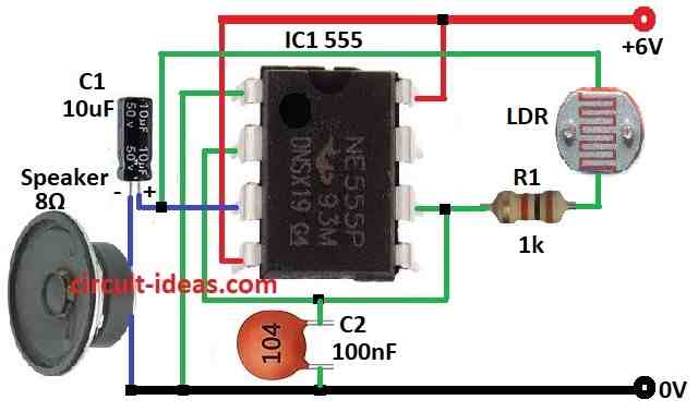
- Take all parts from as per the circuit diagram.
- Pin 1 of IC 555 goes to ground.
- Pin 2 connect to pin 6.
- Pin 3 connect to ground using capacitor C1 and 8 ohm speaker.
- Pin 4 goes to +6V.
- Pin 6 connect to pin 3 using resistor R1 and LDR in series.
- Capacitor C2 connect from pin 2 to ground.
- Pin 8 goes to +6V.
Note:
This circuit is very simple as sound may not be very nice but it good for learning how to make interactive circuits.
Conclusion:
Simple Light Dependent Screamer Circuit is small project.
It changes light to sound using LDR and 555 IC.
More light gives faster beep and less light gives slower or low beep.