To begin with, this Low Battery Indicator with Buzzer Circuit is very simple and uses basic idea and few parts.
Buzzer make sound when battery is low and warn us and it help us to know when to change the battery so device do not stop suddenly.
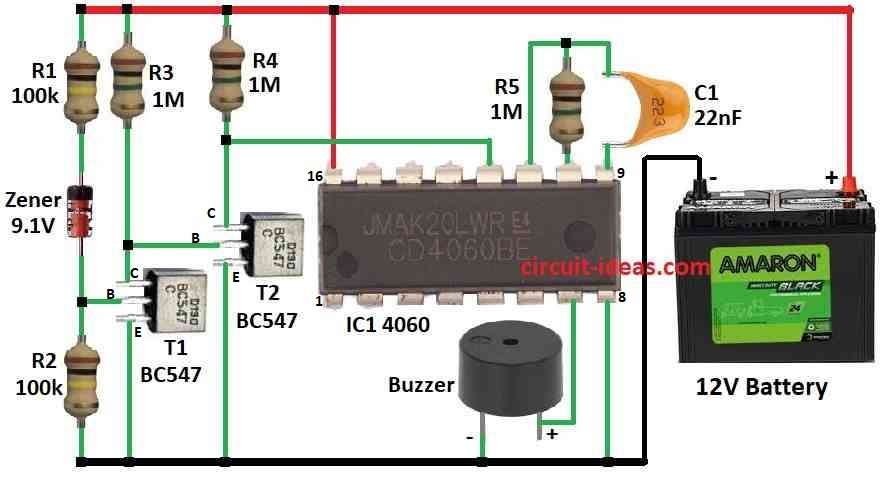
Circuit Working:
Parts List:
| Components | Values | Quantity |
|---|---|---|
| Resistors (All resistors are 1/4 watt) | 100k | 2 |
| 1Meg | 3 | |
| Capacitors | Ceramic 22nF | 1 |
| Semiconductors | IC 4060 | 1 |
| Transistors BC547 | 2 | |
| Zener diode 9.1V | 1 | |
| Buzzer | 1 | |
| 12V Battery | 1 |
Circuit working of a Normal Voltage:
This circuit works like low battery detector and it makes beep-beep-beep sound when battery goes below 10V.
First, transistor stay ON because Zener diode conduct when battery is above 10V and then transistors Vce is very low like 0.3V so second transistor stays OFF.
Also, 1M resistor pull reset pin of IC 4060 HIGH when second transistor goes OFF and when reset pin is HIGH then 4060 stop working with no clock pulse.
Then pins 9, 10, 11 of IC connect to inside inverters with outside parts like resistor, capacitor where it makes clock pulse; hence, this pulse is repeating signal made by oscillator.
Pin 12 act like ON/OFF for oscillator and HIGH on pin 12 stop pulses going to divider inside IC.
When the battery voltage drops below 10V, the Zener diode stops working, as a result, the first transistor turns OFF, while the second transistor turns ON.
Consequently, the reset pin goes LOW and the IC 4060 restarts; after that, the oscillator runs again and generates clock pulses.
Inside the IC flip flops divide this pulse and pin 7 give slow pulse with 1 Hz which is good for buzzer sound.
As a result, this 1 Hz HIGH-LOW pulse make piezo buzzer go beep-beep-beep.
Formulas:
We can use the IC 4060 to build a simple low battery alarm circuit.
Buzzer sound depend on frequency when the battery is low and buzzer make sound.
How to set circuit with frequency:
IC 4060 have inside oscillator and it uses resistor R and capacitor C to set frequency.
Frequency formula:
f = 1 / (2.3 × R × C)
where:
- f is the frequency in Hz
- R is the resistor in ohms which connects to pin 10
- C is the capacitor in farads which connects to timing pin
To make buzzer work right we should choose correct R and C, as right R and C value gives proper buzzer sound when battery is low.
Also, this way we can tune circuit for low battery warning.
How to Build:
To build a Low Battery Indicator with Buzzer Circuit follow the below mentioned connections process:
- First, pin 7 of IC 4060 connects to one leg of buzzer and other leg of buzzer goes to ground
- Next, pin 8 of IC 4060 connects to ground.
- Then pin 9 connects to capacitor C1 and pin 10 goes to resistor R5
- Now pin 11 join with pin 9 and 10.
- After that, pin 12 connects between collector of T2 and resistor R4
- Then pin 16 connects +12V battery supply and from +12V to ground
- Finally, resistor R1 connects to 9.1V Zener diode and resistor R2 in series
Transistor T1:
- T1 collector goes to +12V through resistor R3, base connects between Zener diode and resistor R2 and then emitter connects to ground
Transistor T2:
- T2 collector goes to +12V through resistor R4, base connects between resistor R3 and T1s collector and then emitter connects to ground
- Positive battery terminal connects to circuit of +12V and negative battery terminal goes to ground
Extra Notes:
- Circuit uses very little current when not beeping to around 30µA and while beeping a current is still low with under 1mA
- Want quieter sound? then use piezo diaphragm instead of buzzer and with diaphragm we may need higher frequency to adjust R and C
Safety Tips:
- Safe to use at right voltage and if building then solder carefully and avoid hot parts and keep room ventilated
- Also, use correct battery and throw old one properly and do not change circuit unless we know electronics well.
Conclusion:
To conclude, this Low Battery Indicator with Buzzer Circuit give warning when battery is low also we should use it safely as it helps save our battery powered devices.