This project for Simple Machine Gun Sound Generator Circuit using IC 555 which makes circuit like machine gun sound, short and fast bursts.
Here, 555 chip give quick electric pulses and controls the sound timing and this pulses turn into sound and make “rat-a-tat-tat” noise.
If want loud sound? its easy! just add amplifier and make sound big and strong.
Circuit Working:
Parts List:
| Components | Values | Quantity |
|---|---|---|
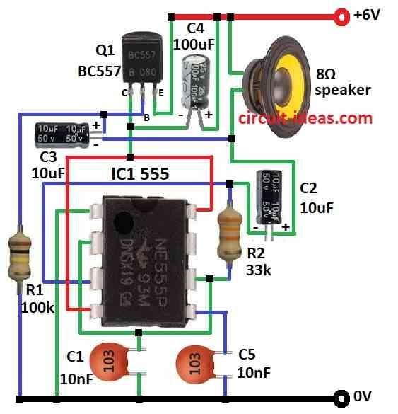
| Resistors | 100k, 33k 1/4 watt | 1 each |
| Capacitors | Ceramic 10nF | 2 |
| Electrolytic 10μF 25V | 2 | |
| Electrolytic 100μF 25V | 1 | |
| Semiconductors | IC 555 | 1 |
| Transistor BC557 | 1 | |
| 8Ω Speaker | 1 |
When the 555 IC operates in astable mode, it generates continuous square-wave pulses, consequently, these pulses produce a sound that resembles repeated machine-gun firing.
Here how circuit works:
First, pin 3 generates the output signal, while C1 and R2 control its frequency.
Then C2, C3 and C4 shapes the signal and turn simple square wave into sound like drum or cannon, after that, C3 makes transistor Q1 turn OFF when pin 3 is high.
Now C4 then drop voltage to 555 IC fast and this make output voltage goes down and also C4 cuts voltage strongly and this drop make gun like sound.
Hence, when output goes low then Q1 turns ON again and process repeat, so 555 chip keeps sending fast pulses and speaker change these into machine gun sound.
Formulas:
To make machine gun sound we have build circuit using 555 IC in astable mode which gives fast pulses.
Use this formula for frequency (f):
f = 1.44 / (R1 + 2R2) * C
where:
- R1 and R2 are resistors
- C is timing capacitor
Duty Cycle D:
D = R2 / (R1 + 2R2)
This shows how long signal stays ON vs OFF and to make sound like fast gunfire then change R1, R2 or C.
Smaller values give higher frequency and sound fires faster.
How to Build:
To build a Simple Machine Gun Sound Generator Circuit follow the below mentioned steps for connections purpose:
- First, collect all parts shown in circuit diagram.
- Next, connect pin 1 of IC 555 to ground.
- Then connect pin 2 to pin 6 of IC 555 and also connect capacitor C1 from pin 2 & 6 to ground.
- After that, connect pin 3 to pin 2 & 6 through resistor R2.
- Connect pin 4 and pin 8 to +6V supply.
- Now connect pin 5 to ground using capacitor C5.
- Also, connect pin 6 again to pin 2 and pin 3.
- Then connect collector of transistor Q1 to pin 4 and pin 8 of IC 555, connect base of Q1 to ground using resistor R1 and then connect emitter of Q1 to +6V supply.
- Connect positive leg of capacitor C4 to +6V and negative leg to collector of Q1.
- Finally, connect positive leg of capacitor C3 to base of Q1 and negative leg between one end of 8Ω speaker and positive leg of C2.
Safety Tips:
Conclusion:
To conclude, this Simple Machine Gun Sound Generator Circuit using IC 555 makes machine gun like “rat-a-tat-tat” sound; also IC 555 is in astable mode and capacitors and transistor work together to shape signals.
Furthermore, speaker plays the final sound like real rapid fire.
Leave a Reply