This article show a special trick to make a Simple Metal Detector Circuit, which uses simple circuit not like other circuits and needs only one transistor.
The circuit find metal by catching signal from a normal radio.
What is a Metal Detector:
A metal detector is an electric circuit that checks whether metal is nearby, as it works through electromagnetic induction; and when metal comes close, it changes the frequency of a special circuit.
Also, people use metal detectors in many places such as factories, treasure hunting, airport security and historical excavation sites.
Circuit Working:
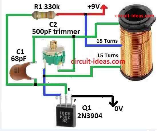
Parts List:
| Components | Values | Quantity |
|---|---|---|
| Resistor | 330k 1/4 W CFR | 1 |
| Capacitors | Ceramic 68pF | 1 |
| Trimmer 500pF | 1 | |
| Semiconductor | Transistor 2N3904 | 1 |
| Search Coil as given in the text | 1 |
Below we can explain how metal detector circuit works:
First, take plastic round base 3 to 4 inch wide and wind wire on it 30 times and this will make coil called L1.
Then connect L1 to circuit using three wires which will become search coil or sensor.
We also use it to find buried metal and it fixes the coil to the end of a long wood or plastic stick.
Hence, to find metal at inside walls keep whole circuit inside small box so we can carry easily.
The circuit work when metal come close and disturb the electromagnetic field made by coil L1, also when metal come L1s value and frequency both changes.
If possible, use small battery radio near circuit, as radio catches this change and make loud sound.
First, tune the radio to a local station until we hear a beat or small flutter sound; and then turn capacitor C1 slowly until we hear a low beat or chirp, which means it is set right.
When metal is near, the sound changes more and this will help find hidden metal, also circuit find changes in field made by L1 when metal is there.
Furthermore, radio make these changes louder so its easy to know metal is there, also, capacitor C1 need to adjust correct to get strong signal.
Formula:
Below formula helps to find starting frequency of metal detector circuit:
f = 1 / 2π√(L * C)
where:
- The resonant frequency, represents as f measures how fast a circuit vibrates in Hertz (Hz), also it is the natural speed at which the circuit works best.
- 2π is two times pi to about 3.14159 which comes often in wave and vibration math.
- L is coils inductance in henries H where coil stops quick change in current.
- C is capacitors value in farads F where capacitor keep electric charge for short time.
- √ mean square root.
How formula work:
Multiply L and C which then take square root and then multiply by 2π and do 1 divided by that number which then gives f.
If we make C or L bigger frequency f go down and if C or L is smaller then f goes up.
Hence, this help set circuit to correct working speed.
How to Build:
The following are the connections steps for building a Simple Metal Detector Circuit.
Make Oscillator Coil L1:
- First, take plastic round bobbin 3 to 4 inch wide and wrap 30 turns of insulated wire on it.
- Also, be sure wire is tight and neat.
Connect Coil to Circuit:
- After that, use three wire cable to join coil L1 to circuit and now L1 starts sensing coil
Build Circuit on Breadboard:
- Next, put transistor on breadboard and find out which pin is emitter, base and collector.
- Then connect coil L1 to emitter and collector sides.
- Now add resistors if needed to set transistor properly, also put variable capacitor C1 into the circuit.
- If required, change value of C1 to adjust circuit tuning.
Set Up Radio Receiver:
- Keep the radio near the circuit, connect it with a proper wire and make sure we position the antenna correctly for a strong signal.
Power the Circuit:
- After that connect battery to give power and check that transistor can handle battery voltage.
Test the Circuit:
- Now turn the circuit ON and set radio to local FM/AM station.
- Now listen to speaker we may hear soft beat or flutter sound.
- Then turn C1 slowly until low beat or chirp sound come, this means tuning is working.
Try Metal Detecting:
- Bring circuit close to metal.
- If metal comes near, the radio sound changes and the beat becomes faster or louder, which means the circuit detects metal.
Improve the Circuit:
- To make circuit better try different values for capacitor or make small changes in design.
- Keep testing to find what gives best result for metal finding.
Conclusion:
To conclude, anyone can make working Simple Metal Detector Circuit by following these above steps.
Also, if we need for different metal finding job we can change circuit like use different capacitor values or change coil design.