Simple Micro Flasher Circuit using IC CD 4093 is easy way to make LED blink for many indicators.
CD 4093 has four NAND Schmitt trigger gates inside.
It runs on 6V battery and need few parts only which is very simple and good.
Flashing happens because one NAND gate turn LED ON and OFF steady.
Circuit Working:
Parts List:
| Component | Specification | Quantity |
|---|---|---|
| Resistors | 330k, 330Ω 1/4 watts | 1 each |
| Capacitors | Electrolytic 10µF 25V | 2 |
| Semiconductors | IC CD 4093 | 1 |
| Diode 1N4148 | 1 | |
| LED any 5mm 20mA | 1 | |
| Power Source 6V Battery | 1 |
CD4093 chip got four Schmitt NAND gates but this circuit use only one gate to make signal change all time.
First put capacitor C1 and resistor R1 to make timing.
C1 and R1 control how fast signal goes up and down.
Capacitor C2 keep power steady.
When power is ON C1 fill with electricity through R1.
When C1 voltage reaches certain point then NAND gate changes the output.
Diode D1 help C1 discharge right to keep signal going.
Output goes to LED1 and makes it blink.
LED1 connect with resistor R2 to stop too much current.
Blink speed depends on R1 and C1 values and change them to change blink speed.
Formulas with Calculations:
Below is the simple formulas for Micro Flasher using CD 4093 IC:
Frequency (f) = 1 / (1.38 × R1 × C1)
where,
- f is the blinking speed
- R1 is the 330k ohm = 330,000 ohm
- C1 is the 10 microfarad = 10 × 10⁻⁶ F
Put values:
f = 1 / (1.38 × 330,000 × 10 × 10⁻⁶) = 0.22 Hz
Meaning LED blink about 1 time every 4.5 seconds.
To make blink faster then we can make R1 or C1 smaller.
How to Build:
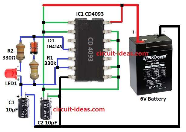
To build a Simple Micro Flasher Circuit using IC CD 4093 following steps are required for connections of the circuit:
- Pins 1, 2, 8, 9, 12, 13 of IC1 go to positive power supply.
- Pins 5 and 6 of IC1 are join together.
- Pin 4 of IC1 connect to diode D1 anode and diode D1 cathode connect to one end of resistor R1 and other end of R1 connect to pin 6 of IC1.
- Resistor R2 and LED1 connect in parallel to diode D1 and resistor R1.
- Pin 7 of IC1 connect to ground GND
- Capacitor C1 positive connect to pin 6 of IC1 and LED1 and negative of C1 go to ground.
- Capacitor C2 positive go to positive power supply and negative to ground.
- Pin 14 of IC1 connect to +6V battery positive and battery negative to ground.
Conclusion:
This Simple Micro Flasher Circuit using IC CD 4093 is easy and uses low power.
We can only use one NAND gate from IC.
Change blink speed by changing R1 or C1 values.
Circuit is good for indicators, alarms or for low power signals.