Imagine our voice is a tiny whisper going into a microphone.
This Microphone Preamplifier Circuit using Two Transistors works like a small megaphone; it makes the whisper louder so the main amplifier can clearly boost our voice.
Circuit Working:
Parts List:
| Components | Values | Quantity |
|---|---|---|
| Resistors (All resistors are 1/4 watt unless specified) | 100k | 1 |
| 120k | 1 | |
| 100Ω | 1 | |
| 10k | 1 | |
| 12k | 2 | |
| Capacitors | Ceramic 100nF | 3 |
| Electrolytic 10µF 25V | 1 | |
| Semiconductors | Transistor BC547 | 1 |
| Transistor BC557 | 1 |
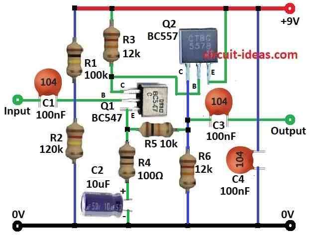
To begin with, this is a simple microphone preamplifier circuit using two BJTs bipolar junction transistors in a common emitter setup.
Here, the microphone connects to the input through capacitor C1 which blocks DC and lets only the AC audio signal pass to the base of transistor Q1 BC547.
Resistor R1 100k sets the bias current for Q1 and capacitor C2 10µF passes the amplified signal from Q1s collector to the base of Q2 BC557 while blocking DC.
Resistor R3 12k sets the bias current for Q2 and Q1 amplifies the microphone weak signal and Q2 boosts it further.
Also, resistors R3 and R5 10k control the circuits gain with a voltage gain of about 12 (R3 ÷ R5).
Furthermore, capacitor C4 100nF removes DC from the output, allowing only the amplified AC signal to pass.
Overall, this circuit is a simple example of how to build a microphone preamp using basic transistors.
Formulas:
This is a general formula for a two transistor preamplifier using common emitter amplifiers.
First Stage Q1 BC547:
Voltage Gain Av1:
Av1 = –RC / RE
where,
- RC is the collector resistor of Q1
- RE is the emitter resistor of Q1
Current Gain Ai1:
Ai1 = β × (RC / RE)
where,
- β is the current gain of the transistor
Second Stage Q2 BC557:
Voltage Gain Av2:
Av2 = –RC2 / RE2
where,
- RC2 is the collector resistor of Q2
- RE2 is the emitter resistor of Q2
Current Gain (Ai2):
Ai2 = β × (RC2 / RE2)
where,
- β is the current gain of the transistor
Note:
Therefore, these formulas may change based on specific needs like desired gain or input impedance.
How to Build:
To build a Microphone Preamplifier Circuit using Two Transistors we need to follow the below mentioned steps for connections:
- First, connect the base of Q1 BC547 to the input through capacitor C1 100nF and resistor R1 100k to the positive supply, connect the collector of Q1 to resistor R3 12k and capacitor C2 10µF and then connect the emitter of Q1 to ground through resistor R4 100Ω and capacitor C2 10µF.
- Then connect the base of Q2 BC557 between Q1s collector and resistor R3, connect the collector of Q2 to ground and connect the emitter of Q2 to the positive supply.
- After that, connect capacitor C3 100nF between the emitter of Q2 and the output and also connect capacitor C4 100µF between the output and ground.
- Now connect resistors R1 and R2 in series from the positive supply to ground and also connect resistor R4 between resistors R5 and R6.
Safety Note:
- Be careful while working with electronics and if anyone is unsure about electronics then better ask an expert or get help.
Conclusion:
To conclude, this Microphone Preamplifier Circuit using Two Transistors is a simple and educational project, as it uses a common emitter design to boost weak signals from a microphone and resistor values help control the gain.
Finally, it is a great way to learn how basic audio amplification works.
Leave a Reply