This article show how to make a Simple Morse Key Circuit using IC 555, which is an easy circuit and is good for Morse code practice.
Also, IC 555 can work in many ways, in this project it work as astable multivibrator which means it make signal by itself and there is no need for outside trigger.
Circuit Working:
Parts List:
| Components | Values | Quantity |
|---|---|---|
| Resistors | 3.3k, 15k 1/4 watt | 1 each |
| Capacitors | Electrolytic 10μF 25V | 1 |
| Ceramic 47nF | 1 | |
| Semiconductors | IC 555 | 1 |
| Speaker 8Ω | 1 | |
| Morse Key | 1 |
To begin with, IC 555 work as astable multivibrator and it make high and low signals without outside trigger.
Then resistor R1 and capacitor C2 control how fast it oscillate (frequency); change R1 or C2 to change sound tone, resistor R2 and C2 control how long sound stays ON and OFF (timing), and it decides how long speaker makes sound and stays silent.
Hence, these timing make Morse code dot and dash and when key is pressed the circuit is complete and IC 555 start to oscillate.
Morse Key Codes:
Morse code is way to send text using short and long signals called dots and dashes or dits and dahs and it is named after Samuel Morse who helped make early telegraph system.
Below are the morse key codes:
A: ·- B: -··· C: -·-· D: -·· E: · F: ···- G: –· H: …. I: .. J: .— K: -.- L: ··· M: — N: -. O: — P: .– Q: –.- R: .-· S: … T: – U: … V: …. W: .– X: -··- Y: -·– Z: ..–
Formulas:
We use IC 555 in astable mode for Morse key circuit by pressing key starts the signal and releasing stops it and this make signal go ON and OFF again and again (oscillate).
Circuit use these formulas:
Frequency (f):
f = 1.44 / (R1 + 2R2) × C
where,
- R1 and R2 are resistors
- C is timing capacitor
- f is how fast signal go up and down
Duty Cycle D:
D = R2 / (R1 + 2R2)
D show how long signal stay high and lo and we can change R1, R2, C to set tone and timing we want.
How to Build:
To build a Simple Morse Key Circuit using IC 555 we need to follow the below mentioned steps:
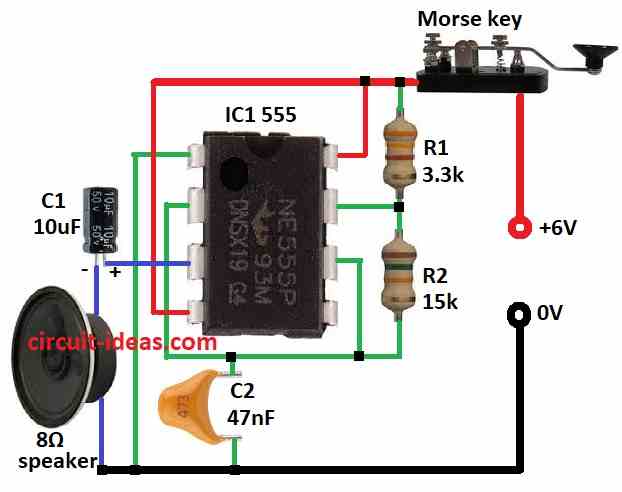
- First, collect all parts like in circuit diagram.
- Then pin 1 of IC 555 goes to ground.
- After that, pin 2 connect to pin 6 and also capacitor C2 connect to ground from pin 2 and pin 6.
- Next, pin 3 connect to ground through capacitor C1 and 8 ohm speaker.
- Now pin 4 connect to +6V power and pin 8 also connect to +6V.
- Also, resistor R2 go between pin 6 and pin 7 and then pin 7 connect to +6V through resistor R1.
- Finally, connect Morse key to +6V line.
Conclusion:
Overall, this Simple Morse Key Circuit uses an IC 555 to generate sound signals for Morse code practice.
Also, when the user presses the key, the circuit produces a tone through the speaker.
Therefore, the circuit helps beginners learn Morse code in a simple way, moreover, it uses only a few components, so it is easy to build and test.
Hi.
I find this schema and i think i like it. I try to build it and hope i will have fun it.
Thank you very much for it.
I”m going to try to find some parts and than i start to building.
Hi Vladimir,
thanks for your comment my friend, and I know you will definitely get success designing your own Morse code. Best of luck. take care.
Regards,