This post is for a Simple Neon Lamp Fuse Blow Alarm Circuit which helps us know when the fuse in the AC mains line gets open or blown.
Normally, when the fuse is healthy, current flows through it and the load works in normal condition, when the fuse blows, the load stops working but at this time the neon lamp turns ON and by giving us a visual indication.
Therefore, this circuit is very useful in home appliances, power boards, stabilizers and industrial control panels where quick fuse fault detection is important.
This circuit works directly on AC mains voltage and therefore, proper safety is very important during construction, testing and installation.
Circuit Working:
Parts List:
| Components | Values | Quantity |
|---|---|---|
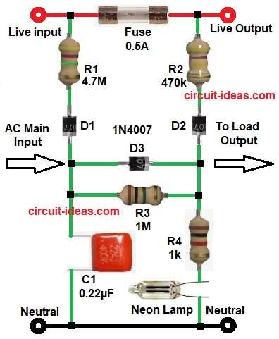
| Resistors (All resistors are 1/4 watt) | 4.7M, 470k, 1M, 1k | 1 each |
| Capacitor | Polyester 0.22µF 400V | 1 |
| Semiconductors | D1, D2, D3 1N4007 | 3 |
| F1 0.5A | 1 | |
| Neon Lamp | 1 |
In the circuit the fuse is connected in series with the AC live line, so during normal condition the AC supply passes through fuse and goes to the load.
When fuse is good the voltage drop across the fuse is almost zero, because of this, the neon lamp does not get enough voltage, so the neon lamp remains OFF.
When fuse is blown the live input side still has AC voltage, but the output side becomes disconnected from the live supply.
Now a voltage difference develops across both sides of the fuse and this voltage reaches the neon lamp through resistors R1, R2, R3, R4, capacitor C1 and diodes D1, D2, D3.
As a result, the neon lamp glows and hence, the user can easily identify that the fuse has blown.
The diodes 1N4007 protect the neon lamp and also help in half-cycle current control.
The capacitor C1 works as a dropper capacitor and limits current without wasting much power.
Resistors R1 and R2 act as high-value for safe current limiting, R3 gives balancing and leakage discharge path and R4 limits current directly to the neon lamp.
How to Build:
To build a Simple Neon Lamp Fuse Blow Alarm Circuit follow the below connection steps:
- First, collect all the circuit parts as in diagram above. Next, start with input side and connect AC live wire to live input terminal marked with L.
- And connect AC Neutral wire to neutral terminal marked with N
- Then start with fuse and connect 0.5A in series with live wire.
- One fuse end goes to AC live input and second fuse end goes to load live output.
- After that, take resistor R1 and diodes D1 section and connect one pin of R1 to fuse input side live.
- Connect second pin of R1 to diode D1 anode and connect D1 cathode to center junction point.
- After that take resistor R2 and diode D3 section and connect one end of R2 to fuse output side live.
- Connect second end of R2 to D3 anode and connect D3 cathode to output center junction.
- Middle link connection connect D2 diode anode to left center point and connect D2 cathode to right center point.
- Resistor R3 connect across the same two center junction points.
- Capacitor section connect one end of C1 to left center junction and connect second end of C1 to neutral line.
- Connect R4 from right center junction to neon lamp top pin and connect neon lamp bottom pin to neutral line.
- Finally, load output take live output from fuse output side and take neutral output directly from neutral line.
Important Safety Note:
- This circuit works directly on AC mains voltage.
- Therefore, use proper insulation, fuse holder and PCB spacing.
- Do not touch the circuit when power is ON.
- Always test with series lamp or isolation transformer.
Conclusion:
To conclude, this Simple Neon Lamp Fuse Blow Alarm Circuit is easy, low-cost and very useful for quick fault indication.
Moreover, it uses very few components and gives instant visual warning through the neon lamp, but one should be careful as the circuit works directly on AC mains voltage
Therefore, it is a good circuit for domestic and industrial AC systems and also the capacitor dropper design keeps power loss low and improves efficiency.