This Simple Piezo Buzzer Circuit make sound in new way.
It is easy to make and need only few parts like:
- One transistor which works like small switch
- One coil is like a tiny electromagnet
- One small speaker part and a piezo transducer to change electricity to vibration
It make high sound like a whistle.
This circuit is special because coil makes the sound to keep going and is not like other circuit with resistor and capacitor only.
What is a Piezo Buzzer Circuit:
Simple electronic circuit that make sound using piezo buzzer is called piezo buzzer circuit.
Piezo buzzer mostly use in electric things to give sound alert, alarm or beep.
Main part of piezo buzzer is piezo element which make sound by shaking when voltage goes in.
Circuit Working:
Parts List:
| Category | Item | Quantity |
|---|---|---|
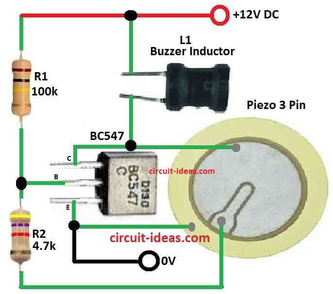
| Resistors | 100k CFR | 1 |
| 4.7k CFR | 1 | |
| Semiconductors | Transistor BC547 | 1 |
| Buzzer Inductor | 1 | |
| Piezo 3 Pin | 1 |
When we look at piezo buzzer circuit diagram we see transistor T1 and inductor are main parts.
The piezo used here has 3 pins, the middle pin give feedback and buzzer coil is put in good way to make sound stronger.
Transistor turn ON when power comes in and this makes piezo element work with the coil.
Then transistor and piezo turns OFF fast.
The middle pin of piezo send signal to ground and this stop the transistor.
After this transistor turn ON again and this cycle keep happening which make buzzing sound again and again.
Middle pin of piezo is very important because without it sound does not work well.
That is why 3 pin piezo is needed not 2 pin.
The coil get signal from transistor and fill with magnetic energy, then coil release this energy to make strong AC.
This AC connect to piezo pins positive and negative sides and make piezo vibrate fast and loud like sharp whistle.
Piezo must be fixed nicely inside case to make sound louder.
To make right sound frequency circuit work like crystal oscillator and the piezo here act like ceramic crystal.
It is hard to know exact frequency but design work like crystal oscillator.
For best result piezo should touch bottom of case and case need a small hole to about 7mm wide for sound to come out.
Formulas:
Below is easy formula for Simple Piezo Buzzer Circuit:
Resonance frequency happen when circuit work best with AC (changing current) and this is the formula used:
Frequency = 1 / (2π√(L × C))
where:
- f is frequency in hertz Hz
- 2π means 2 times pi a math number about 3.14
- √ means square root
- L is inductance and how much coil resist changes in current in Henry H
- C is capacitance how much capacitor store energy is in Farad F
How to Build:
Below are easy steps to build a Simple Piezo Buzzer Circuit
- Put NPN transistor T1 on breadboard.
- Connect ferrite inductor to collector pin of transistor.
- Connect 3-pin piezo transducer to base and emitter of transistor.
- Add resistors and capacitors like shown in circuit diagram.
- Use wires to join all parts as per the circuit.
- Connect power supply to right place on breadboard and be sure voltage is correct for circuit.
Piezo Transducer Installation:
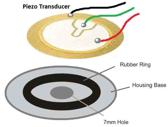
- Take small box and make hole in it of about 7mm wide.
- Put 3-pin piezo at bottom of box.
- Place soft rubber ring on piezo the ring should be 30% smaller than piezo.
- Use glue to fix piezo and ring in box and check they stay in right place.
Testing and Adjust:
- Turn ON the power and watch how the circuit work.
- If circuit is good we can hear buzzing sound from piezo.
- If we want different sound then change resistor or capacitor value.
- To make sound louder then move piezo inside box little bit until sound better.
Note:
- We can make simple piezo buzzer that gives special sound and feedback by using these steps.
- Circuit can be changed to get right frequency.
References:
BUZZER BASICS -TECHNOLOGIES, TONES,AND DRIVE CIRCUITS
Design Techniques to Increase a Piezo Transducer Buzzer Audio Output