This Simple Regulated Adjustable Power Supply Circuit using IC 723 show how to make one simple power supply circuit, which can change voltage up and down.
We can use one chip call LM723 with some people say IC 723, this chip is good and it take power from plug and makes it stable.
Also, we can turn one knob to choose how much voltage come out.
This circuit is very helpful for many electronics project.
Circuit Working:
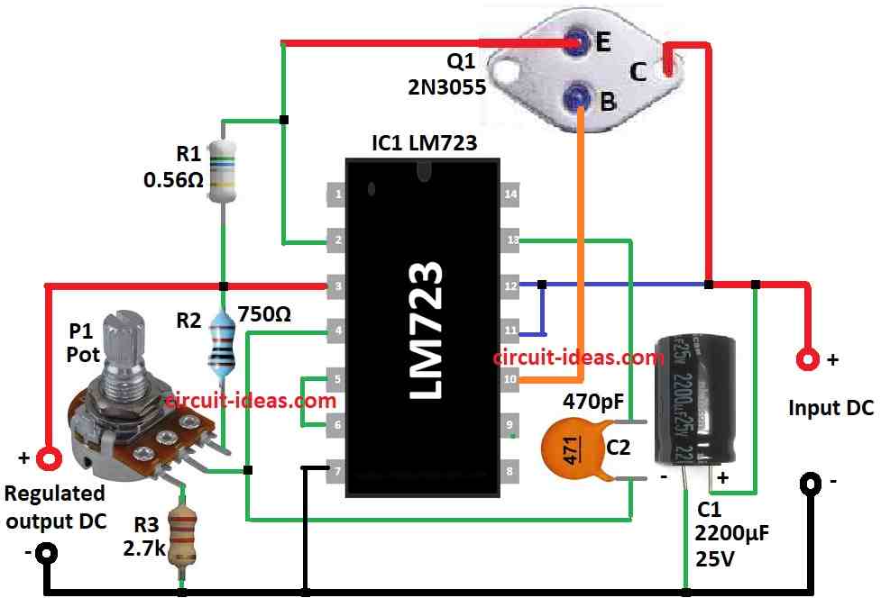
Parts List:
| Component | Quantity |
|---|---|
| Resistors | |
| 0.56Ω1W | 1 |
| 750Ω 1/4 watt | 1 |
| 2.7k 1/4 watt | 1 |
| Potentiometer 1k | 1 |
| Capacitors | |
| Ceramic 470pF | 1 |
| Electrolytic 2200µF 25V | 1 |
| Semiconductors | |
| IC LM723 | 1 |
| Transistor 2N3055 | 1 |
Potentiometer used for adjusting inside reference level of IC 723 which help output voltage stay stable like shown below:
When we slowly move middle arm wiper of potentiometer near ground it change voltage at inverting pin of op-amp and then output voltage goes up.
When we move pot arm down output voltage does not stay same like reference.
Feedback system works to change voltage at inverting pin to match voltage from pot.
If voltage across pot pin goes down then output voltage goes up to balance and if we move pot arm more down then voltage drop more.
So IC make output voltage goes more high, for example if pot arm move two third down then feedback voltage become one third of output voltage.
So output become 3 times more than reference voltage and it keep inverting pin at right voltage.
This way s pot and feedback help to adjust output voltage and keep it stable.
How to calculate output voltage:
If we want fixed voltage we can remove potentiometer and use two resistors R1 and R2 as voltage divider which we can see in the circuit diagram.
Formula:
Below are the formulas for Regulated Adjustable Power Supply Circuit using IC 723:
Output Voltage = Reference Voltage × (R1 + R2) / R2
where,
- Reference Voltage means steady voltage from inside IC.
- R1 connect from output to inverting pin.
- R2 connect from inverting pin to ground.
This make reference voltage go to non-inverting pin of IC 723 op-amp.
This formula show how to get constant output voltage.
If we want output voltage less than 7V we can change formula number, but should not be too low.
Remember: IC 723 can not give less than 2V which is the minimum.
So if we want 2V output then formula is:
Output Voltage = 2 × (R1 + R2) / R2
Understanding Current Limit in IC 723:
IC 723 can also control how much current goes to load.
We use special resistor to sense current and if current is too much then it stops extra current.
This keep current safe.
Formula to find current limit resistor is:
Rsc = 0.66 / Max Current
How to Build:
To build a Simple Adjustable Power Supply Circuit using IC 723 follow the below mentioned steps:
Get Components Ready:
- First collect all parts we need like IC, resistors, potentiometer etc.
Put IC 723:
- Place IC 723 on breadboard or PCB.
- Connect pins same like datasheet say.
- Main pins to connect: input voltage, ground, output, reference and adjust pin.
Check Voltage Divider:
- Use two resistors: R1 and R2.
- R1 goes from output to inverting pin of op-amp.
- R2 goes from inverting pin to ground of negative line.
- This setup make reference voltage.
Add Potentiometer:
- Put potentiometer in circuit.
- One side goes to positive and other one side to ground.
- Middle pin wiper connects to inverting pin.
- This let us change voltage slowly.
Add Current Limiting Resistor:
- Use this formula: Rsc = 0.66 / Max Current
- Use resistor with same value.
- Put it in series with load to stop extra current.
Finish Op-Amp Wiring:
- Connect non-inverting pin to reference voltage.
- If needed add extra resistors for more stable output.
Connect Power Supply:
- Now connect power source.
- Be careful with positive and negative sides.
Test Circuit:
- Before giving full power check all wires and parts.
- Then give power slowly.
- Use multimeter to check voltages and check if it look okay.
Adjust Output:
- Turn potentiometer to change voltage.
- See if output voltage stay steady as we want.
Test Current Limit:
- Connect load on output.
- Check if current stay under the limit.
- If not then change current resistor and fix it.
Note:
- Be safe and use good wire cover for insulation.
- Check for short circuit.
- Work in place with good air.
- If anyone is new to electronics then ask someone who know well.
Conclusion:
So by using IC 723 for adjustable power supply is small and smart way to get stable DC voltage we can change.
Because of feedback and filter parts voltage stay same even when input or load changes.
This Simple Regulated Adjustable Power Supply Circuit using IC 723 is useful and trusted.
People use it in many places like for sensitive devices, lab equipment and also in audio systems.
Leave a Reply