Simple TV Remote Tester Circuit is small tool like A doctor for ones remote.
It uses one infrared sensor like eye for light which we cannot see and to check if remote give signal when one presses the button.
If signal arrives small light turns ON or buzzer make beep sound which means remote is working good.
This circuit is very easy to build as it uses parts like LED or buzzer to indicate signal.
Circuit Working:
Parts List:
| Component | Quantity |
|---|---|
| Resistor | |
| 12k 1/4 watt | 1 |
| Capacitors | |
| Electrolytic 10µF 25V | 1 |
| Semiconductors | |
| IR Sensor IC TSOP1738 | 1 |
| LED (any 5mm, 20mA) | 1 |
| Buzzer | 1 |
| 9V Battery | 1 |
This small remote tester checks if the remote is working or not.
It is an easy to use and help sees if remote is okay.
It uses one IR sensor called TSOP 1738 and this sensor has one small photodiode and signal amplifier inside plastic case.
Sensor work with 5 volt and when there is no signal the output is 5V and when it get 38kHz IR signal from remote its output go down to 0V.
One just need to point remote to sensor and press any button.
If remote works LED will light and buzzer will make and indicating sound.
That mean remote is good.
Formula:
TSOP1738 is popular IR receiver chip which catches IR signals from remote controls.
People use it in TV remote testers and other small projects.
This chip find special IR signals same like ones from remotes.
It see 38kHz pulsed signal which most remotes use.
Inside TSOP1738 it has small amplifier, gain control and photo sensor.
All this help to see only one type of signal which is usually 38kHz.
Here how it work in TV remote tester:
TSOP1738 Output Behavior:
Mostly TSOP1738 have these features:
Output Voltage:
When it see IR signal (38kHz) output go low which is around 0V.
When no signal is detected then output stay high like 5V which is same as power.
How to Read Output:
- If output (Vout) = 0 → IR signal is there.
- If output (Vout) = Vcc (5V) → No IR signal.
Note:
TSOP1738 works good because it only listen for 38kHz signal.
This make it easy way to check remote is working or not.
How to Build:
To build a Simple TV Remote Tester Circuit follow the below mentioned steps:
Circuit Explain:
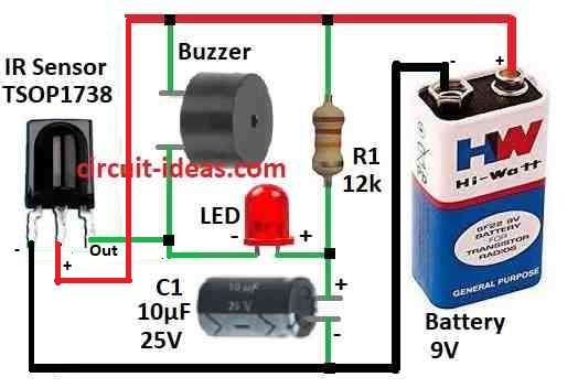
Connect TSOP1738 Vcc pin to power (+).
- Connect TSOP1738 ground pin to GRD of the circuit
- Put one resistor R1 between Vcc and output pin of TSOP1738.
- Connect output pin to LED with resistor same as R1 or new one.
- LED long leg anode connects to resistor and short leg cathode connects back to TSOP output.
- Connect buzzer between output pin and power (+).
How to Build:
- Put all parts on breadboard or PCB same like in diagram.
- Be sure LED and buzzer connected right way because polarity is important.
- Check all wire and part connection with no mistake no short circuit.
- On breadboard use jumper wires to connect parts.
- On PCB solder parts carefully not too hot.
- Give 5V power to the circuit.
How to Test:
- Take one working remote and point it to sensor.
- Press any button on remote.
- LED will blink and buzzer will beep, this show remote is working.
Note:
- Follow all the steps slowly and carefully and handle all parts gently.
- Check again before putting the power ON and then the remote tester will work fine.
Conclusion:
Simple TV Remote Tester Circuit is an easy and useful tool to check if remote is working or not.
It uses IR sensor and small things like LED or buzzer to show if signal come from remote.
Because it simple and easy to build, both hobby people and repair person can use it.
With only few parts and simple design this tester helps one know if remote is okay or not.
Leave a Reply