If we want to make sound generator circuit for cheap?
Then this post for Simple Universal Signal Generator Circuit show easy way to build using transistors.
These type of circuits are good for:
- Fixing broken radio or amplifier.
- Testing our other electronic project.
- Learning how electronic make sound.
We can make this circuit at a very low cost.
What is a Universal Signal Generator Circuit:
Universal Signal Generator circuit is helpful tool for testing and fixing electronic circuits.
It can make different kind of electrical signals.
Not like special signal generator for only one job but this circuit can make many type of signals.
So it is useful for engineer, technician and people who like electronics.
Circuit Working:
Parts List:
| Category | Description | Quantity |
|---|---|---|
| Resistor | All 1/4 W CFR | |
| 5.6k | 1 | |
| Potentiometers | ||
| 2M | 1 | |
| 2k | 1 | |
| Capacitors | ||
| Ceramic 0.0022µF | 1 | |
| Ceramic 0.022µF | 1 | |
| Semiconductors | ||
| Transistor BC547 | 1 | |
| Transistor BC557 | 1 | |
| Battery 9V | 1 |
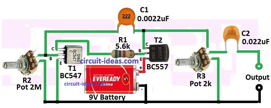
This is an easy circuit diagram with short explanation of how transistor audio signal generator works:
Two transistor Q1 and Q2 are used like amplifier.
They make and boost the audio signal.
Control knob R2 changes the sound frequency or tone.
Turning R2 change resistance so tone also changes.
Another control knob R3 adjust the signal strength like amplitude.
Capacitor C1 and C2 help pass only AC audio signal as they block DC.
Q2 and C2 gives the final output of the signal.
Formulas:
Using parts in this circuit we can make astable multivibrator or oscillator which become universal signal generator.
This circuit can make many kind of signals like pulse and square wave so it is good for testing and signal making.
Frequency Formula:
Astable multivibrator gives frequency like this:
f = 1.44 / (R1 + 2 * R2) * C
where:
- R1 is resistor going to base of NPN transistor BC557.
- R2 is resistor from NPN collector to base of PNP transistor BC547.
- C is total of capacitor C1 and C2 used for timing.
Change the potentiometer and we can change the frequency.
So this simple circuit can make square wave at different speed.
How to Build:
The build a Simple Universal Signal Generator Circuit follow the below connections steps:
- First collect all parts and tools we need.
- Think where to put the transistors inside small box for best working.
- Put control knobs R2 and R3 in right place on circuit board.
- Add all other parts carefully and follow steps correct for good circuit building.
- After all parts are placed build the full circuit inside small metal box.
- Check all wire and part connection to ensure there is no mistake.
- After finish turn ON the signal generator and see if it works.
- R2 control the sound frequency or tone.
- R3 control how strong the signal is.
- To be sure it works right compare the output signal with known good one like another signal generator.
- If something is different then change and fix it.
Testing and Changing:
- When building follow correct wiring like in the circuit diagram.
- To get sound or tone we want turn ON the circuit and adjust R2.
- To make sound louder or softer adjust R3.
- To make circuit more perfect compare output with real trusted source and adjust as needed.
Note:
- This is just simple guide an exact part values can change for our need.
- We must calculate values depending on what frequency we want and how we use it.
Conclusion:
Simple Universal Signal Generator Circuit can be used in many place like telecom work, audio testing, electronics, learning and research, schools and labs.
It is helpful tool for people working with electronics.
It can make many kind of signals and help test or check circuits.
Leave a Reply