This small and Simple USB Lamp Circuit show how to make as easy night light using USB port from computer or laptop.
To make this only few parts are needed:
USB plug like one on phone charger.
One LED it gives small light and does not use much power.
One resistor it control how bright the LED shine.
This circuit is good when we need little more light in dark place or when power goes OFF.
Circuit Working:
Parts List:
USB Type A is also called Standard A connector which looks flat and rectangle shape.
This USB Type A is old one but still is used in USB 3.0, 2.0 and 1.1.
Mostly this USB Type A is used in computer and USB hub as main connector.
We should not see USB A socket on device for input but it is mostly for output from PC or hub to other things.
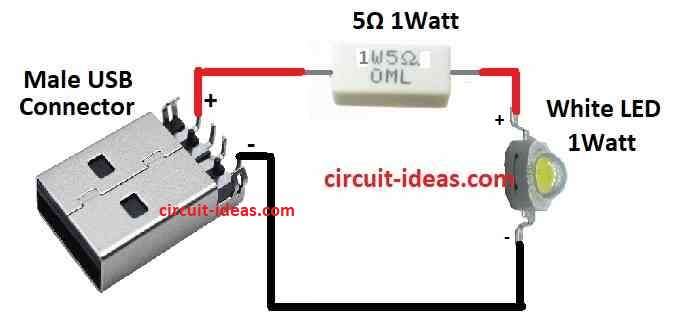
This circuit is very easy and it is only used for LED, USB Type A male plug and one resistor of 5 ohm 1 watt.
The 5 ohm resistor is good for 3.3V white LED with1 watt which controls current to 25mA.
We can use any old or spare USB wire to make this connection.
This small USB lamp is good for laptop or computer when power suddenly goes out.
Just plug it in USB port and it will give small light which is useful for checking fuse box, motherboard or small place where big torch or lamp is not easy to carry.
Formula:
This formula from Ohms Law is very important to understand how USB lamp work:
R = V / I
where:
- R mean resistance it show how much resistor resist current as it is in ohms Ω.
- V is voltage across the part and is measured in volts V
- I is current going through part in amps A.
Ohms Law help us find resistor value for LED circuit:
R = (Vsource – VLED) / ILED
here:
- R in ohms is the resistor we need.
- Vsource is voltage from USB or battery in volts.
- VLED is LED forward voltage drop.
This number we can find in LED datasheet which is usually between 1.8V to 3.4V.
ILED is how much current LED needs which is also in datasheet.
For small LEDs it is normally 10 mA to 30 mA.
This formula help choose correct resistor so LED light up safely.
How to use the formula:
1. Get the data:
First check power source voltage from datasheet which is Vsource.
Also find LEDs forward voltage VLED and current ILED from LED datasheet.
2. Put values in formula:
Now use the formula:
R = (Vsource – VLED) / ILED
Put the numbers we found into the formula.
3. Find resistance:
Solve the formula and the answer is R the resistance in ohms Ω.
This is the resistor value we need for your LED to work safely.
How to Build:
To Build a Simple USB Lamp Circuit follow the below mentioned steps:
Find the USB Type ‘A’ Connector:
- Ensure the plug is male USB Type ‘A’.
- It should be flat and rectangle shape which we can see it many times on USB cables.
Collect the parts:
- Get one bright white LED and 5 ohm 1 watt resistor.
- Check if resistor can handle LED power.
Choose good resistor:
- To keep current near 25mA and make LED work safe use 5 ohm 1 watt resistor.
- Check LED specification and use Ohms Law if needed for different value.
Connect resistor to LED:
- Take resistor and connect one leg to long leg anode of an LED.
- Other leg of resistor connect to Vcc power line from USB Type ‘A’ connector.
Connect LED short leg:
- Short leg of LED cathode goes to ground line of USB Type ‘A’.
Build the circuit:
- Use jumper wires to make circuit on computer or small board.
- Follow steps to connect all parts.
- If not using solder all parts on PCB to make it strong.
Plug in USB:
- Now connect USB Type ‘A’ male plug to laptop USB port or any USB power.
Test the circuit:
- After connecting, LED should turn ON and It will give light when needed.
Use:
- This USB lamp is helpful when there is no power or in small space.
- Just plug it and get quick light where there is no need of big torch.
Conclusion:
This Simple USB Lamp Circuit project is good for beginners or hobby people.
It is simple but fun way to learn basic electronics.
It also shows how useful USB connection can be.
Leave a Reply