This Variable Power Supply Circuit using 7805 or 7812 ICs work like smart adapter; it uses chip like 7805 or 7812 which normally gives 5V or 12V and add some other parts like resistor and turning knob like potentiometer.
Hence, these extra parts help change the voltage up or down so we can set what our project needs, also it feel like we have many adapter in one.
But making variable power like this is not best way, better and more easy is to use real adjustable voltage chip for good result.
Circuit Working:
Parts List:
| Components | Values | Quantity |
|---|---|---|
| Variable Resistor | Potentiometer 10k | 1 |
| Capacitors | Ceramic 0.01µF | 1 |
| Ceramic 0.001µF | 2 | |
| Electrolytic 4.7µF 25V | 1 | |
| Electrolytic 2200µF 35V | 1 | |
| Electrolytic 4700µF 35V | 1 | |
| Semiconductors | IC 7805 (or 7812 or 7824) | 1 |
| Zener diode 15V 1.3W | 1 | |
| Coil inductor powder core (32 turns of 0.75mm) | 1 | |
| Bridge rectifier 1N5402 | 4 | |
| Transformer 24V 2A | 1 |
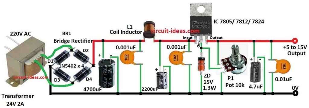
This power supply uses 7805, 7812, or 7824 voltage chip and last two number in chip name indicates max voltage it give.
Also, circuit is good as it stop noise hum, clean the power and use special filter called C-L-C (capacitor-inductor-capacitor).
When we pick the coil core be sure it work in right frequency like company say.
L1 coil uses powder core and has 32 round of 0.75mm wire and transformer take 240V in and gives 24V 2A out.
Bridge rectifier use 4 diodes and this diode must handle more current than transformer give or they can break.
Also, C1 is a big filter capacitor and L1 and C3 help clean the power more and C2 and C4 are for to remove ripple decoupling capacitors.
7805 chip U1 use Zener diode ZD1 and turning resistor R1 to make output voltage change and when we turn R1 voltage goes from 7805 level to 7805 + Zener diode voltage.
For example 7805 + 10V Zener can give from 5V to 15V and we can change 7805 and Zener diode to get other voltages, Zener diode must be at least 1.3 Watt power.
Formulas:
From this circuit we can use some easy formula like below:
Transformer Secondary Voltage:
Vsecondary = Vprimary × Nsecondary / Nprimary
where:
- Vprimary 220V AC input side
- Nsecondary is how many turns in the output coil
- Nprimary is how many turns in the input coil
Note: This formula works for perfect transformer but actual one may have some voltage drop.
DC Voltage After Rectifier (Vdc):
Vdc = Vsecondary × √2 – Diode Voltage Drop
Diode drop usually 0.7V per diode and in bridge rectifier two diodes drop voltage so total around 1.4V loss
Output Voltage After Regulator (Vout):
For fixed voltage chips like 7805, 7812, 7824:
Vout = Number in the chip name (5V, 12V or 24V)
For adjustable output using potentiometer and Zener diode:
Vout = Vref × (1 + R2 / R1)
where:
- Vref is Zener voltage like 15V
- R1 is resistance between wiper and Zener
- R2 is resistance between wiper and ground
Note: This formula gives rough value only but real output may change because of load and parts not perfect.
How to Build:
To build a Variable Power Supply Circuit using 7805 or 7812 ICs we need to follow the below mentioned assembling steps:
Transformer and Rectifier:
- First, transformer gives 24V from secondary side and this 24V AC connects to bridge rectifier which change it to DC.
Filtering:
- After that, DC still have some ripple like noise and so we have used capacitors C1, C2, C3 and C4 to make it smooth.
- Now C1 is big main filter and L1 and C3 work together to clean the power even more.
Voltage Control:
- Voltage regulator chip keep output voltage steady.
- Zener diode ZD1 and turning resistor R1 let us change voltage and when we turn R1 output voltage change for example 7805 and 10V Zener can give 5V to 15V.
Important Note:
- Be very careful with high voltage mains and always follow safety rules and if we do not know how to build circuit then check proper diagram or ask expert for help.
Conclusion:
To conclude, we can make a Variable Power Supply Circuit using 7805 or 7812 ICs chip with some simple parts.
Also, by adding a turning resistor potentiometer we can change the output voltage in a certain range and this is useful for different electronics projects.
But be sure the parts do not get too hot and check the voltage is okay for our circuit and if they are not then things can break.
Leave a Reply