A Wailing Siren Circuit using IC 555 is simple to make sound like real siren, going up and down in pitch.
The sound come from 555 IC making pulses at certain speed (frequency).
Circuit Working:
Parts List:
| Category | Description | Quantity |
|---|---|---|
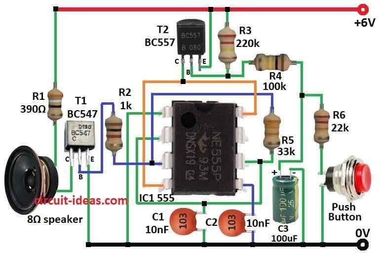
| Resistors | 390Ω, 1k, 220k, 100k, 33k, 22k 1/4 watt | 1 each |
| Capacitors | Ceramic 10nF | 2 |
| Electrolytic 100μF 25V | 1 | |
| Semiconductors | IC 555 | 1 |
| Transistor BC547 | 1 | |
| Transistor BC557 | 1 | |
| Speaker 8Ω | 1 | |
| Push Button | 1 |
555 IC work in astable mode with no need of outside trigger as it oscillate by itself.
R3, R4 and C3 control how fast it oscillate.
Pin 3 of 555 give high low voltage because C1 charges and discharge through R5.
Transistor T1 BC547 work like switch and is controlled by pin 3 output.
When T1 is ON and output is high then speaker get current and makes sound.
R3, R4 and C3 set pitch of siren sound which changes them to change pitch.
Transistor T2 BC557 control power to 555 IC.
When push button pressed then T2 turns ON and power goes to 555 and then the circuit starts.
Release button then T2 is OFF and and then the circuit stops.
Pin 3 keeps changing voltage and turn T1 ON/OFF as C1 charges and discharges.
Speaker make pulsing sound and pitch depend on how fast C1 charge/discharge and is set by R3, R4 and C3.
Formulas:
Main goal is make is the siren sound by using 555 IC in astable mode and by changing frequency output.
Use this formula for frequency (f):
f = 1.44 / (R1 + 2R2) × C
where,
- R1 and R2 are resistors.
- C is timing capacitor.
Duty cycle D tell how long high and low sound stay:
D = R2 / (R1 + 2R2)
We can change R1, R2 and C to adjust siren sound and how it behaves.
How to Build:
To build a Wailing Siren Circuit using IC 555 follow the below mentioned process for connections:
- Put all parts like in circuit diagram.
- Connect pin 1 of 555 IC to ground.
- Connect pin 2 and pin 6 together.
- Connect capacitor C1 from pin 2 & 6 to ground.
- Pin 3 goes to base of transistor T1 through resistor R2.
- Pin 4 goes to 6V positive supply.
- Pin 5 connect to ground with capacitor C2.
- Pin 6 connect to pin 3 with resistor R5.
- Pin 8 goes to 6V positive.
- T1 collector connect to 8 ohm speaker and resistor R1 and then to 6V.
- T1 base connect to pin 3 with resistor R2.
- T1 emitter goes to ground.
- T2 collector connect to pin 4 and 8 of IC.
- T2 base connect to resistor R4 and positive of capacitor C3.
- C3 negative goes to ground.
- T2 emitter goes to 6V.
- Between R4 and C3 connect resistor R6 and push button in series to ground.
Safety Tips:
- Use right value parts.
- Do not short power supply and be very careful.
Conclusion:
Making this Wailing Siren Circuit using IC 555 is fun and good for learning.
We can change sound pitch by changing parts.
This small project show how 555 IC make sound effects.
Leave a Reply