White LEDs are very common now for lights.
They are used in electronics, car displays and home lights because they save power, last long and work well.
But for long life and best work the power must be managed well.
IC TPS61161A is special chip which is the LED driver for this job.
It can power many white LEDs in series and it gives steady current so light stays same and color is good.
This chip has features like changeable current, wide input voltage and high efficiency and it helps make LED circuits easy and strong.
This article for Simple White LED Driver Circuit using TPS61161A talks about IC how it works, why it is good and where to use it.
By knowing this chip the designers can make better LED lighting systems.
Circuit Working:
Parts List:
| Component Type | Value | Quantity |
|---|---|---|
| Resistors | 10Ω 1/4 watt | 1 |
| 560Ω 1/4 watt | 1 | |
| Capacitors | Electrolytic 1μF | 2 |
| Ceramic 220nF | 1 | |
| Semiconductors | IC TPS61161A | 1 |
| Coil 22μH | 1 | |
| Schottky Diode MBR0540T1 | 1 | |
| LEDs White 5mm 20mA | 8 |
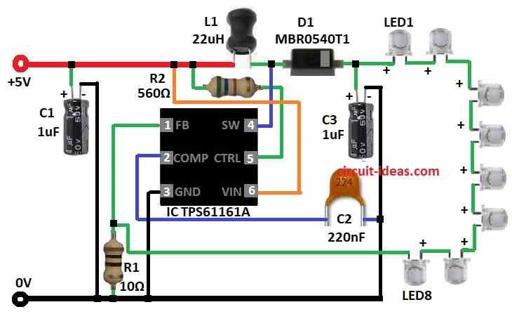
TPS61161A LED driver can run up to 8 white LEDs with only few extra parts.
It works at fixed 600 kHz to reduce output ripple.
It runs on 2.7V to 18V and has 38V open LED safety inside.
LED current is set using outside resistor R1 and 200 mV feedback control.
Brightness can goes down by sending PWM signal to control pin.
For full brightness it control pin connects to Vin through resistor R2.
Both Vin pin and control pin get Vin power through R2.
LEDs get power from Vin through diode D1 and inductor L1.
L1 and D1 connect to switch pin.
LEDs negative side goes to feedback pin and other side of R1 goes to ground to check current.
COMP pin gives output of error amplifier and one capacitor connects there to help regulator work right.
Formulas:
Using TPS61161A we use these formulas to design and check white LED driver circuit:
1. LED Current ILED:
Use Ohms Law:
ILED = (VLED − VD) / RLED
where,
- VLED is the LED forward voltage
- VD is the Diode drop to around 0.3V for Schottky
- RLED is the total series resistance for R1 + others
2. Inductor Current IL:
IL = (VOUT × D) / (L × f)
where,
- VOUT is the LED output voltage
- D is the duty cycle
- L is the Inductor of 22µH
- f is the switching frequency
3. Output Voltage VOUT:
VOUT = VIN / (1 − D)
where,
- VIN is the input voltage like 5V
- D is the duty cycle
4. Ripple Voltage on Capacitor (Vripple):
Vripple = ILED / (f × C3)
where,
- ILED is the LED current
- C3 is the output capacitor with 1µF
- f is the frequency
5. Capacitor Charge Time (t):
t = R × C × ln((Vsupply − Vf) / Vsupply)
- R is the series resistor
- C is the capacitance
- Vsupply is the 5V input
- Vf is the final voltage on capacitor
6. Power Output POUT:
POUT = VOUT × ILED
This gives power sent to LEDs
Use these formulas to check circuit performance and change parts if needed for good brightness and efficiency.
Always check values carefully while designing.
How to Build:
To build a Simple White LED Driver Circuit using TPS61161A follow the connections steps below:
- Take TPS61161A IC and other parts shown in circuit diagram.
- Pin 1 connect to GND through R1 10Ω and also connect LED cathode strings to Pin 1.
- Pin 2 connect to one side of C2 220nF and other side of C2 to GND.
- Pin 3 connect direct to GND.
- Pin 4 connect between Inductor L1 22µH and Diode D1 MBR0540T1.
- Pin 5 connect to 5V through R2 560Ω.
- Pin 6 connect direct to 5V supply.
- C1 1µF connect between 5V and GND.
- L1 22µH connect between 5V and Pin 4.
- D1 MBR0540T1 anode goes to pin 4 and cathode to LED anode strings.
- C3 1µF connects positive to D1 cathode and LED anodes and negative to GND.
- LEDs positive side connects to C3 (+) and D1 cathode and negative to pin 1.
Conclusion:
Simple White LED Driver Circuit using TPS61161A can run up to 8 white LEDs with few parts.
It works from 2.7V to 18V and with 38V safety for open LEDs.
It switches at 600 kHz to reduce ripple.
PWM helps to dim brightness and R1 controls LED current.
It is with small size WSON package and is good for tight space.
Very useful and reliable for modern LED lighting.
References:
TPS6116x White LED Drivers With Digital and PWM Brightness Control in 2-mm x 2-mm
WSON Package
Leave a Reply