This Simple Two Transistors Amplifier Circuit using 1.5V Battery works like loudspeaker for small sounds.
It uses 2 small parts called transistors and 1.5V battery to make weak sound strong.
It is simple mini amplifier which are good for small projects for making music sound better.
Circuit Working:
Parts List:
| Category | Item | Quantity |
|---|---|---|
| Resistors (All resistors are 1/4 watt unless specified) | 2.2M, 10k | 1 each |
| Capacitors | Electrolytic 1µF 25V, 220µF 25V | 1 each |
| Semiconductors | Transistors BC547, BC557 | 1 each |
| ON/OFF Switch | 1 | |
| 64Ω Speaker | 1 | |
| Battery 1.5V | 1 |
This circuit gives clear sound and has many good features.
How it works:
Two transistors connect directly and this gives big gain means the loud sound.
Speaker has high impedance of 64 ohm which still gives good sound even with low 1.5V battery.
Speaker works like motor and coil makes magnet force with amp turns and pushes speaker cone.
More amp turns is louder sound.
Amp turns can be made of two ways:
Coil with few turns + high current
Or coil with many turns + low current.
Transistor action:
2.2M resistor turns on BC557.
BC557 base is 0.6V below 1.5V to around 0.9V.
This turns on BC547.
BC547 pulls current to positive and lowers voltage on 2.2M resistor.
Speaker has resistance so BC557 cant fully raise BC547.
At rest only 0.05mA goes through speaker which is very small.
When working signal makes voltage swing from 0V to 0.9V.
This 0.9V goes to speaker and makes sound.
Formulas:
Basic Formulas for Transistor Amplifier Circuit:
1. Voltage Gain (Av):
Shows how much output is bigger than input.
Av = Vo / Vi
where,
- Vo is the output voltage
- Vi is the input voltage
2. Gain in dB decibels:
Shows gain in sound level units.
Gain (dB) = 20 × log10(Av)
3. Collector Current (Ic):
Tells how much current goes through transistor.
Ic = (Vcc – Vce) / Rc
where:
- Vcc is the supply voltage like battery 1.5V in this circuit
- Vce is the voltage from collector to emitter
- Rc is the resistor connected to collector
Note:
These formulas may change a bit depending on how circuit is made and how transistors are connected.
For real audio amplifier better to use higher voltage which is more than 1.5V.
Always think about power and parts while designing the circuit.
How to Build:
To build a Simple Two Transistors Amplifier Circuit using 1.5V Battery follow the below mentioned steps:
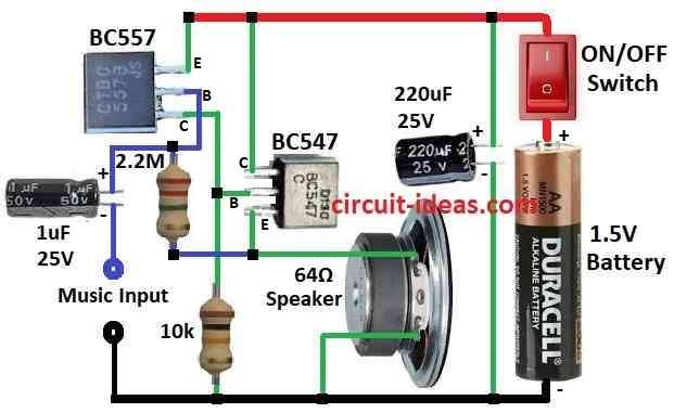
Transistor Connections:
- Connect collector of BC547 to +1.5V battery.
- Connect emitter of BC547 to one side of speaker.
- Connect other side of speaker to ground.
- Connect base of BC547 to collector of BC557 and also to ground through 10k resistor.
- Connect base of BC557 to emitter of BC547 using 2.2M resistor.
- Connect audio input to base of BC557 using 1µF capacitor.
- Put 220µF capacitor across battery with (+) and (-) sides).
- Add ON/OFF switch to +1.5V battery wire.
- Connect negative side of battery to ground.
- Turn ON the circuit.
- Connect audio like phone sound to input.
- Listen to speaker.
- Change input volume and check the sound.
Note:
- This circuit always makes weak sound strong.
- Speaker gets enough power to make sound.
- We can change parts for better sound or different needs.
Conclusion:
This is Simple Two Transistors Amplifier Circuit using 1.5V Battery which makes one sound louder and second helps match the load.
This type of circuit is good for basic audio jobs.
References:
A 1.5V Current-Mode Operational Amplifier Using Level Shifter Technique