Sometimes when our circuit power is ON a big current comes suddenly.
This sudden current can damage parts like IC, capacitor and transistor.
To stop this we make Slow Voltage Rise Power Supply Circuit.
This circuit gives voltage slowly but not full at once.
So circuit become safe and work is quite reliable.
Circuit Working:

Parts List:
| Component | Value | Quantity |
|---|---|---|
| Resistors | 2.7k 1/4 watt | 1 |
| 240Ω 1/4 watt | 1 | |
| 3.3k 1/4 watt | 1 | |
| Capacitors | Electrolytic 10uF 25V | 1 |
| Ceramic 0.1uF | 1 | |
| Semiconductors | IC1 LM317 | 1 |
| Transistor BC557 | 1 | |
| Diode 1N4002 | 1 |
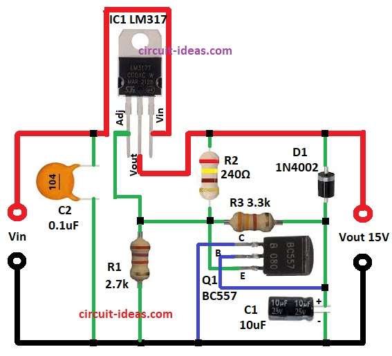
The above circuit is made with LM317 adjustable regulator which gives max 1A current.
LM317 output follow formula: Vout = 1.25 (1 + R2/R1)
In the circuit diagram above R1 is 2.7k, R2 is 240 ohm through this we get output near 15V.
Capacitor C2 removes high frequency noise.
Capacitor C1 gives stability and filtering.
Soft start happen by transistor Q1 2N2907 with resistor R3.
When power is ON Q1 pull control pin low and output does not comes fast.
As C1 charge slowly and Q1 conduction reduces then output rise smooth to 15V.
Diode D1 put reverse to protect IC from capacitor discharge.
Input must be little more than output as in this circuit, input to is about 18V or 20V DC.
Formula with Calculations:
For LM317 regulator output voltage formula is:
Vout = 1.25 (1 + R2/R1) + (Iadj x R2)
where,
- R1 is 2.7k
- R2 is 240 ohm
- Iadj is very small to about 50uA
Vout = 1.25 (1 + 2700/240)
Vout = 15.31
In this circuit transistor and resistor help capacitor charge slow so output goes with slow start up to 15V
How to Build:
To build a Slow Voltage Rise Power Supply Circuit follow the below steps for connections:
- First collect all parts shown in circuit diagram.
- Connect pin 1 ADJ of LM317 goes to Vin.
- Connect capacitor C2 one side to ADJ pin and other side to ground.
- Connect pin 2 Vout of LM317 to point of resistors R1, R2, R3 and emitter of transistor Q1.
- Connect pin 3 Vin of LM317 goes to resistor R2, diode D1 and also to 15V output.
- Transistor Q1 emitter goes to ground and collector goes to output with resistor R3.
Conclusion:
This Slow Voltage Rise Power Supply with LM317 give safe 15V DC output with smooth rising.
It stop sudden current when power is ON and protect the devices.
Circuit is good for audio amplifier, digital circuit and other delicate electronics.
Leave a Reply