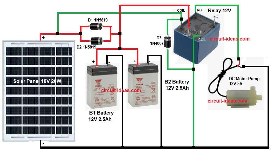
This project is about Solar Water Pump Circuit using Battery and Relay; it uses one 18V 20W solar panel, two small 12V batteries, one relay and diodes.
The circuit can run a 12V DC water pump and battery stores power from solar panel and relay controls when pump run; also it is a very simple circuit and is easy to build and is good for small garden or fish tank.
Circuit Working:
Parts List:
| Components | Quantity |
|---|---|
| Solar Panel 18V 20W | 1 |
| Schottky Diode 1N5819 | 2 |
| Rectifier Diode 1N4007 | 1 |
| Battery 12V 2.5Ah Lead Acid | 2 |
| Relay 12V | 1 |
| DC Motor Pump 12V 3A | 1 |
Solar panel gives around 18V in sunlight and D1 and D2 are Schottky diodes 1N5819 and they stop reverse current from battery to panel.
Then panel charges both batteries B1 and B2 each with 12V 2.5Ah and relay coil which is 12V and when solar or battery power is available then the relay pulls in.
After that, relay common pin connects pump to battery and normally open NO contact closes and pump gets 12V to run.
Now D3 1N4007 protects relay coil from back EMF and then pump runs only when relay pulls in.
When voltage is low then relay drops and pump stops and this protects battery from deep discharge and finally, the relay turns the pump ON and OFF automatically based on the solar power or battery voltage.
Formulas with Calculation:
Solar panel current:
Panel = 18V 20W
I = P ÷ V = 20 ÷ 18 = 1.11A
Battery energy:
Each battery = 12V 2.5Ah
Energy = V × Ah = 12 × 2.5 = 30Wh
Two batteries in parallel = 30Wh + 30Wh = 60Wh
Pump power:
Pump load = 12V 3A
Power = V × A = 12 × 3 = 36W
Estimated run time:
Run time = Total battery energy ÷ Pump power
= 60Wh ÷ 36W
= 1.66 hours
So the etimated run time 1.66 hours approx.
How to Build:
To build a Solar Water Pump Circuit using Battery and Relay follow below steps for connection:
- First, take all the parts as shown in circuit diagram.
- Next, connect solar panel positive to diode D1 and D2 anode and then connect diode D1 and D2 cathode to B1 and B2 battery positive line.
- After that, connect solar panel negative directly to battery negative line.
- Then connect relay coil pin 1 to battery positive and connect relay coil pin 2 to ground through diode D3 1N4007 reversed across coil.
- Now connect relay common pin to battery positive and connect relay normally open NO pin to pump positive wire and then connect pump negative wire directly to battery negative.
- Finally, use thick wire for pump because it draws 3A.
Conclusion:
To conclude, this is very simple and useful project for Solar Water Pump Circuit using Battery and Relay, also only one relay and few diodes needed.
Here, solar panel charges batteries and relay controls pump safely and it is good for small home projects which is easy to build even for beginners.

Leave a Reply