A Temperature Difference Based Relay Switch Circuit compares the temperature of two different points and then switches a relay when the temperature difference reaches a set value.
This circuit is useful in solar water heaters, cooling fans, battery temperature monitoring, incubators and industrial heat control systems.
In this circuit, the LM741 operational amplifier works as a comparator and two diodes act as temperature sensors.
The circuit senses the voltage difference created by the temperature change and then drives a transistor and relay and as a result, the load turns ON or OFF automatically.
Because the circuit uses simple components, it is easy to build and is with low in cost, moreover, the sensitivity can be adjusted with a preset resistor.
Circuit Working:
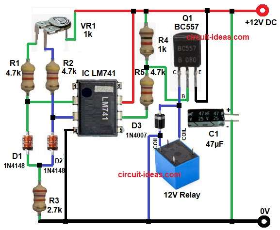
Parts List:
| Components | Values | Quantity |
|---|---|---|
| Resistors | 4.7k 1/4 watt | 3 |
| 2.7k, 1k 1/4 watt | 1 each | |
| Preset 1k | 1 | |
| Capacitor | Electrolytic 47µF 25V | 1 |
| Semiconductors | IC LM741 | 1 |
| Transistor BC557 | 1 | |
| Diodes 1N4148 | 2 | |
| Diode 1N4007 | 1 | |
| 12V DC Relay | 1 | |
| Power Supply 12V DC | 1 |
First, D1 and D2 1N4148 work as temperature sensor diodes, because diode forward voltage changes with temperature and each diode gives voltage based on its heat.
Normally, silicon diode voltage drops around 2 mV for every 1°C temperature rise, so if one diode gets more hot than the other then its voltage becomes slightly lower.
These two sensing voltages go to IC LM741 input pins, where pin 2 is inverting input and pin 3 is non-inverting input.
Next, the op-amp compares both voltages and when pin 3 voltage becomes higher than pin 2 then output pin 6 goes high.
Then transistor Q1 BC557 turns ON, after that relay coil energizes and relay contacts switch the external load like fan, heater or alarm.
But when temperature difference becomes less then op-amp output goes low with Q1 turns OFF and relay releases.
Also, VR1 works as balance and sensitivity adjustment which helps set the switching point as per required temperature difference.
How to Build:
To build a Temperature Difference Based Relay Switch Circuit follow the below connection steps:
- Circuit starts by gathering all the parts as in diagram on the circuit board or PCB.
- Next, start with IC pin 2 and connect between diode sensor network D1 anode side through R1 and VR1 network.
- Then pin 3 connect to diode sensor network D2 anode side.
- Then take pin 4 and connect to ground or negative supply.
- Pin 6 connect to transistor Q1 base network through resistor chain R4 and R5.
- Pin 7 connect to +12V power supply.
- After that, start with transistor Q1 BC557 emitter pin and connect to +12V supply line.
- Base pin connect from LM741 output through resistor network R4 and R5.
- Collector pin connect to one side of relay coil pin.
- Then take 12V relay and one side of coil connect to transistor collector and other side of coil connect to ground.
- Next, take diode D3 and connect across relay coil in reverse bias with cathode to transistor side and anode to ground.
- Also, connect resistor R2 one end from diodes D1 and D2 cathode end and other end of resistor R2 connect to ground.
- Finally, connect capacitor C1 positive from +12V supply line and negative of C1 capacitor goes to ground.
Conclusion:
This Temperature Difference Based Relay Switch Circuit provides an easy and effective way to compare two temperatures and control a load automatically.
The LM741 compares the voltage from two diode sensors and then the transistor drives the relay, as a result, the circuit responds quickly to temperature difference.
Moreover, the adjustable preset makes calibration easy and therefore, this circuit is highly useful for practical temperature control applications in home and industry.