
In today’s world, light effects attract attention and enhance many applications, designers use these effects in toys, decorative lighting, and warning systems.
A Transistor-Based LED Strobe Light Circuit rapidly turns the LED ON and OFF to create an attractive flashing effect; also this simple, low-cost circuit uses only a few components, making it easy for beginners to build and useful for a variety of lighting projects.
Circuit Working:
Parts List:
| Components | Values | Quantity |
|---|---|---|
| Resistors | 470Ω, 220Ω,10k | 1 each |
| Capacitor | Electrolytic 1uF 25V or higher | 1 |
| Semiconductors | Transistor BC547 NPN | 1 |
| Super Bright White LED | 1 | |
| Super Bright Orange LED | 1 | |
| Power Supply 6V DC | 1 |
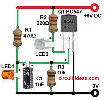
The circuit uses one NPN BC547 transistor and it works as a switch, then resistors control the current, capacitor creates a delay and battery provides power.
When power is ON the capacitor C1 starts charging, so base of transistor gets voltage slowly and then transistor turns ON, and so white LED2 glows.
At the same time capacitor discharges and therefore, base voltage drops and then transistor turns OFF and so white LED2 turns OFF.
Now, the capacitor starts charging again, and the cycle repeats, creating the strobe effect; meanwhile, orange LED1 glows softly to enhance the visual effect.
Formula with Calculation:
Below is the timing formula:
T = R x C
where,
- R is 10,000 ohm
- C is 1 microfarad
T = 10000 x 0.000001
T = 0.01 seconds
So blinking speed of LED is fast.
How To Build:
To build a Transistor Based LED Strobe Light Circuit follow the below steps for connection:
- First, start to collect all the parts as shown in circuit diagram.
- Then Q1 BC547 transistor emitter pin connected directly to ground line, base pin connected to resistor R3 and capacitor C1 negative side.
- After that, capacitor positive side connected between resistor R1 and anode of LED1 and cathode of LED1 connects to GND.
- Also, collector pin connected white LED2 cathode side and anode of LED2 connected to resistor R2.
- At last, battery positive connects to positive supply of the circuit and battery negative goes to ground line.
Conclusion:
Overall, this Transistor-Based LED Strobe Light Circuit offers a simple, reliable and with low cost design that uses only a few components, making it easy for beginners to build.
Finally, this circuit is good for practice which helps to understand transistor working.