
Here is a super easy USB powered battery charger circuit, which requires no microcontroller or fancy parts; hence, we can build it using just a simple resistor, a diode, and NiMH cells.
Also, good for learning, good for small projects and is safe for small rechargeable cells and great for DIY makers.
Circuit Working:
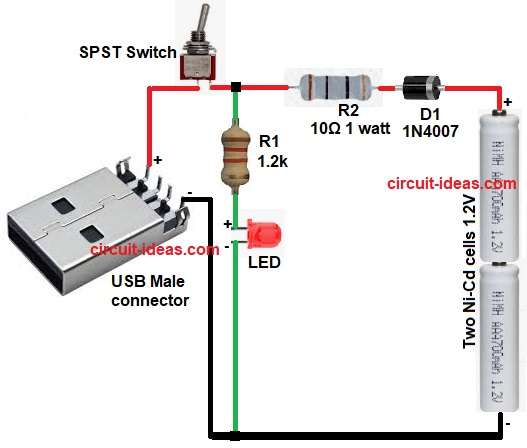
Parts List:
| Components | Values | Quantity |
|---|---|---|
| Resistors | 1.2k , 10Ω 1 watt | 1 each |
| Semiconductors | LED any 5mm | 1 |
| Diode 1N4007 | 1 | |
| SPST Switch toggle | 1 | |
| Two Ni-Cd cells 1.2V each | 2 | |
| USB Male connector | 1 |
To begin with, in this circuit the USB gives 5V and switch connect or disconnect charger; then diode 1N4007 stop reverse current from battery to USB.
After that, R2 resistor limit charging current, R1 resistor and LED show charging is active and then battery slowly charge through resistor.
Now LED glow means current flow.
When battery is full the current drop naturally because of resistor limit and therefore, this circuit is simple trickle charger and not a smart charger.
Formulas with Calculation:
Formula for charging current:
R2 = 10Ω
Charging current I = V / R
I = 1.9 / 10
I = 0.19A or 190mA approx
This current is safe for AA or AAA NiCd or NiMH slow charge.
LED resistor R1 = 1.2k
LED drop approx 2V
Voltage across R1 approx = 5 – 2
Current = 3V / 1200
Current = 2.5mA approx
Hence, this is enough to indicate an LED.
How to Build:
To build a USB Powered Small Battery Charger Circuit following are the connection steps:
- First, collect all the parts as shown in circuit diagram.
- Next, connect USB 5V pin to switch and then join switch output between one end of resistor R1 and R2.
- Now R2 resistor other end connect to anode of diode D1 and cathode of D1 connect to battery positive.
- Also, R1 resistor connect from charging line to LED anode and then LED cathode connect to ground.
- Further, battery pack two cells connect in series and be sure polarity is correct.
- Finally, positive to charger line and negative to ground.
Conclusion:
To conclude, this USB Powered Small Battery Charger Circuit is very simple and works well for slowly charging small batteries, but it is not suitable for Li-ion batteries and only charges NiCd or NiMH batteries.
Furthermore, this circuit costs very little, uses a simple design and works well for hobby learning.