To begin with, this article is for Automatic Light Control Switch Circuit using IC 555, it works with light dependent resistor (LDR).
When light falls on the LDR, its resistance changes, the 555 IC converts this resistance change into a switching signal and drives the relay; the relay can then control a lamp, fan, motor, or other electrical load.
Furthermore, the circuit is useful for automatic street light, garden light, dark sensor lamp or security alarm.
Circuit Working:
Parts List:
| Components | Values | Quantity |
|---|---|---|
| Resistors | 1k 1/4 watt | 1 |
| 3.3k 1/4 watt | 1 | |
| 100k 1/4 watt | 1 | |
| LDR | 1 | |
| Potentiometer 100k | 1 | |
| Capacitor | Ceramic 0.01µF | 1 |
| Semiconductors | IC 555 | 1 |
| Transistors BC547 | 2 | |
| Diode 1N4007 | 1 | |
| Relay 12V | 1 |
This circuit is easy to build, as its parts are easily available in market.
First, the LDR senses the light and the potentiometer sets the light level, then, the 555 IC and two transistors perform the switching and the relay controls the output load.
When light is low the voltage on LDR is small and output of IC1 555 is high and then Q1 turns ON, Q2 stays OFF and relay is OFF.
When light become strong the voltage on LDR goes above a limit and a output of IC1 change with Q2 turns ON and relay gets power.
So relay work according to light on LDR; also this Light Control Switch Circuit is useful for home and industry for automatic light control.
How to Build:
To build a Automatic Light Control Switch Circuit using IC 555 follow the below steps:
- First, take all the parts as shown in circuit diagram
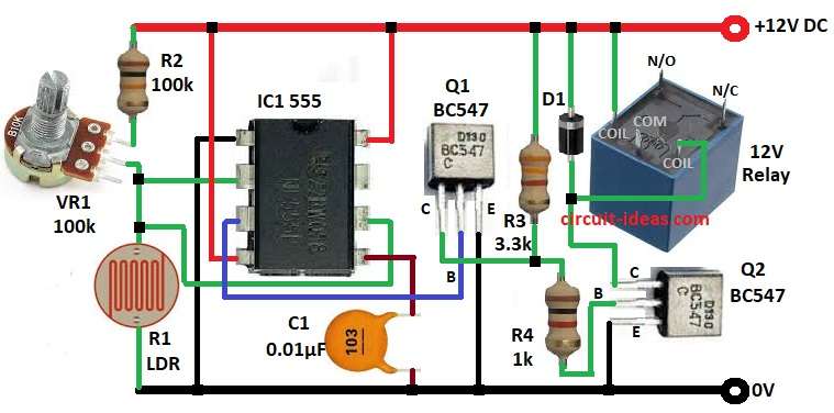
- Next, connect pin 1 of IC1 555 to ground
- Then pin 2 and pin 6 of IC1 555 connect between LDR, potentiometer VR1 and resistor R2
- After that, connect pin 3 of IC1 555 to the base pin of transistor Q1 through resistor R3
- Now pin 4 and pin 8 of IC1 555 connect to positive supply of 12V and connect pin 5 of IC1 555 to GND through capacitor C1
- Also, connect collector of transistor Q1 to positive supply through resistor R3, then connect emitter of transistor Q1 to GND.
- Further, base pin of Q2 transistor connect to collector pin of Q1 transistor through resistor R4, connect collector pin of of transistor Q2 to coil pin of 12V relay and then connect emitter pin of transistor Q2 to GND
- Finally, connect anode of diode D1 to coil pin of relay and cathode of D1 to positive supply
Conclusion:
To conclude, this is a simple project for Automatic Light Control Switch Circuit using IC 555, it uses only one 555 IC, two transistors, one relay and few more components.
Also, it can control any electrical load automatically depending on light or dark and by changing potentiometer value we can set sensitivity.
Furthermore, this type of circuit is good for automatic lights, alarms and energy saving projects.
Leave a Reply