Magnetic levitation is fun science project, in this Electromagnet Levitation Circuit with Hall Effect Sensor, small magnet can float in air without a touch.
Also, it use electromagnet and hall sensor; then this hall sensor see magnet position and transistor gives current to coil; furthermore, this make balance of magnet force and gravity, so magnet look magic floating.
In addition, it is good project for learning feedback system.
Circuit Working:
Parts List:
| Components | Values | Quantity |
|---|---|---|
| Resistors | 10k 1/4 watt | 1 |
| 100k 1/4 watt | 1 | |
| 250Ω 1/4 watt | 2 | |
| Semiconductors | Transistor NPN TIP122, 2N2222 | 1 each |
| Transistor PNP TIP127 | 1 | |
| Hall Effect Sensor A3144 | 1 | |
| Diode 1N4933 | 2 | |
| Electromagnet Coil 24V DC Solenoid coil | 1 |
A3144 hall sensor is the main components of this circuit, it sense magnetic field, when magnet come close and sensor output change.
Then this output goes to transistor amplifier stage and NPN and PNP transistor work together like push pull pair; also they drive current in electromagnet coil.
If magnet goes down then sensor tell circuit to increase coil current and if magnet goes up then sensor tell circuit to decrease the coil current; hence, in this way magnet stay in air at one balance point.
Also, diodes across the coil protect transistor from back emf when current switches fast.
Coil making:
We have used electromagnet coil from 24V DC solenoid, at core its used steel bolts and its size 1/4 to 20.
Then fix bolts into holes drilled in two iron bars size 1 inch by 1/4 inch by 10 inch; then cut bolt heads and make them one inch longer than coil length.
Each coil resistance is 80 ohms and at 24V it take about 6 watts if fully ON; but in normal running current is not always maximum, so, if not then we need to do hand winding of many coils.
Formula:
Wind 250 turns of 35-gauge copper wire around a 1/4-inch diameter bolt to form the coil.
Inductance L can be approximate by formula:
L = (N^2 * μ * A) / l
where,
- N is the number of turns
- μ is the permeability of core
- A is area of coil
- l is the length of coil.
The required current depends on the weight of the magnet and the electromagnet generates a force F given by:
F = (B^2 * A) / (2 * μ0)
where,
- B is the magnetic flux density
- A is the area of pole face
- μ0 is the 4π × 10^-7 H/m.
How to Build:
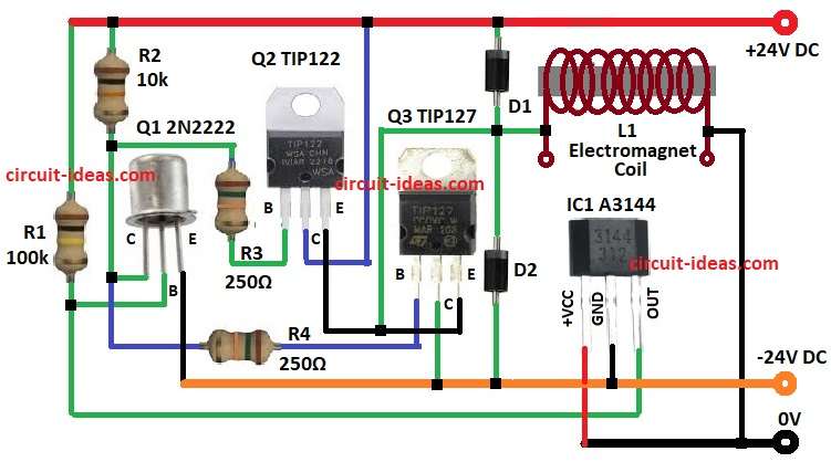
To build a Electromagnet Levitation Circuit with Hall Effect Sensor follow below steps for connection:
- First, collect all parts shown in circuit.
- Next, connect collector of Q1 to +24V by resistor R2, connect base of Q1 between resistor R1 and output pin of IC1 and then connect emitter of Q1 to -24V.
- Now connect collector of Q2 to +24V, connect base of Q2 between resistor R2 and collector of Q1 and then connect emitter of Q2 join with emitter of Q3.
- After that, connect collector of Q3 to -24V and then connect base of Q3 between collector of Q1 and resistor R2.
- Put diodes D1 and D2 in series between +24V and -24V.
- Further, connect one end of coil to emitters of Q2 and Q3 and then connect other end of coil to ground.
- Also, connect pin 1 (Vcc) of IC1 A3144 to +5V, connect pin 2 (GND) of IC1 A3144 to ground and then connect pin 3 (OUT) of IC1 A3144 to base of Q1.
Conclusion:
Overall, Magnetic levitation is fun hobby, it also show real use of control and feedback.
Furthermore, this project show how hall sensor and electromagnet balance magnet weight and with little practice we can make small magnet float stable in air.
Finally, we can improve this Electromagnet Levitation Circuit with a Hall Effect Sensor by using a stronger coil or creating a more stable floating platform; we can also use it for school science projects.
Leave a Reply