Audio amplifier is very important in sound system, as it make weak sound strong for 8Ω speaker and a 12W amplifier uses IC LF351 and push-pull transistors.
This 12 Watt Audio Amplifier Circuit using IC LF351 works on ±12V power and is good for small and medium speakers.
Circuit Working:
Parts List:
| Components | Values | Quantity |
|---|---|---|
| Resistors (All resistors are 1/4 watt unless specified) | 47Ω | 1 |
| 47k | 1 | |
| 4.7Ω | 1 | |
| 2.2k | 1 | |
| 180Ω | 2 | |
| 4.7k | 2 | |
| Potentiometer 10k | 1 | |
| Capacitors | Ceramic 0.0047µF | 1 |
| Ceramic 0.22µF | 1 | |
| Ceramic 10pF | 1 | |
| Ceramic 0.1µF | 1 | |
| Semiconductors | IC LF351 | 1 |
| Transistor PNP TIP127 | 1 | |
| NPN TIP122 | 1 | |
| LED any 5mm 20mA | 1 | |
| Speaker 8Ω | 1 |
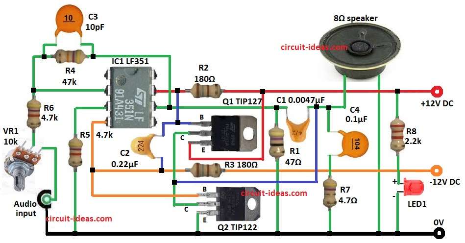
Simple audio amp give 10 to 12W to 8Ω speaker and IC LF351 is preamp and makes input signal strong and stable.
First, signal strength depend on R4 and R6 and then signal goes through C2 to Q1 TIP127 base and Q1 and Q2 TIP122 make push-pull stage.
Then push-pull boost current for 8Ω speaker and R2, R3 and C1 keep output stable.
How to Build:
To build a 12 Watt Audio Amplifier Circuit using IC LF351 follow the below mentioned steps:
- First, gather all parts first as per circuit diagram
- Next, pin 2 of LF351 connect between R4 and R6 (inverting) and also R6 connect from pin 2 to VR1 pot and VR1 connect to audio input and GND.
- Then pin 3 connect to GND via R5 and pin 4 connect to –12V via R3.
- Now pin 6 connect to one end of 8Ω speaker and other end connect to GND and also R4 and C3 in parallel connect between pin 6 and pin 2.
- Also, pin 7 connect to +12V via R2.
- Further, C2 connect from junction of pin 7 and Q1 base to pin 4, then Q1 emitter connect to +12V and collector connect to Q2 collector.
- Next, R8 and LED1 in series connect between Q1 emitter and +12V and GND.
- Then C1 and R1 in series connect from pin 6 to GND and C4 and R7 connect from junction of C1 and speaker to GND.
- Finally, Q2 base connect to pin 4 and emitter connect to –12V.
Conclusion:
Overall, 12 Watt Audio Amplifier Circuit using IC LF351 is for beginners and hobbyists; also few parts make it cheap and easy to build.
Furthermore, IC LF351 with matching power transistors gives solid and clear sound; in addition this circuit is good for small speakers and general audio use.
Leave a Reply