In my earlier article I showed about solar water pump circuit using relay, that design works, but relay makes clicking sound and relay contacts can burn after long use.
So now here is the new version and this project is Solar Water Pump Circuit using Battery and MOSFET instead of relay, as MOSFET has no moving parts, no noise and works faster.
Also, it protects the battery and pump, costs little to build, and works well for watering a small garden or farm;
Furthermore, a very simple idea for solar panel to charge battery, MOSFET switch turn pump ON when voltage is good.
Circuit Working:
Parts List:
| Components | Quantity |
|---|---|
| Resistor 470Ω, 10k | 1 each |
| Solar Panel 18V 20W | 1 |
| MOSFET IRF450 | 1 |
| Fuse 4A | 1 |
| Zener Diode 9V | 1 |
| Schottky Diode 1N5819 | 2 |
| Rectifier Diode 1N4007 | 1 |
| Battery 12V 2.5Ah Lead Acid | 2 |
| DC Motor Pump 12V 3A | 1 |
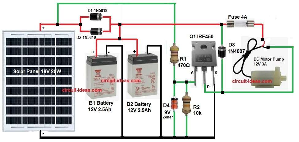
The 18V solar panel gives power when sun is bright and two diodes D1 and D2 stop battery from sending current back to panel.
Then both 12V batteries connect in parallel to increase capacity and B1 and B2 batteries charge slowly from solar panel.
After that, R1 resistor sends small current to MOSFET gate and R2 makes MOSFET gate stable, quiet and safe
Zener diode D4 keeps the gate voltage at safe level.
When battery voltage rises above about 9V then MOSFET gate turns ON and MOSFET Q1 IRF450 conducts and pump motor gets 12V supply.
Also, diode D3 protects MOSFET from motor back EMF and fuse protects pump and wiring from short circuit.
How to Build:
To build a Solar Water Pump Circuit using Battery and MOSFET follow the below connection steps:
- First, assemble all the parts as shown in circuit diagram.
- Next, solar panel positive goes to D1 and D2 input pins and diode outputs go to battery positive terminal and also battery negative goes to ground.
- From battery positive, wire goes to pump switch fuse and fuse output goes to pump motor and pump negative goes to MOSFET drain D3 connection.
- Then motor negative goes to ground through MOSFET Q1.
- MOSFET pins source goes to ground and pin drain goes to pump negative.
- After that, pin gate connects to junction of R1, R2 and Zener diode and other side of R2 and Zener diode connects to circuit Ground.
Conclusion:
Overall, this is very easy and low cost Solar Water Pump Circuit using Battery and MOSFET, also it uses batteries and one MOSFET only.
In addition, parts are simple and circuit can charge battery and run pump by itself with no control needed.
Also, the circuit is good for beginner solar project and work nice in outdoor place and we can change pump or battery later and also can very easily upgrade it.
Leave a Reply