This project shows about a Low Cost 1.2V AA Ni-MH Solar Battery Charger Circuit, as it works with small cheap solar panel and charges the battery safely in sunlight; also it uses only solar panel, diode, resistors and two transistors.
Furthermore, these parts are few which are easy to find and circuit protects battery from too much charge and further the circuit is good for DIY and small electronics projects.
Circuit Working:
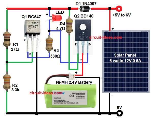
Parts List:
| Components | Values | Quantity |
|---|---|---|
| Resistors (All resistors are 0.25W unless specified) | 27Ω | 1 |
| 3.3k | 1 | |
| 330Ω | 1 | |
| 4.7Ω 1W | 1 | |
| Semiconductors | Solar Cell 6 watts 12V 0.5A | 1 |
| Transistor BC547 NPN | 1 | |
| Transistor BD140 PNP | 1 | |
| LED any 5mm | 1 | |
| Diode 1N4007 0.7V | 1 | |
| Battery Ni-MH 2.4V or 2 × 1.2V AA | 1 |
Solar cell gives around 5V to 6V sunlight voltage, then D1 1N4007 diode stops reverse current at night.
Resistor R4 limits charging current to the battery and Q2 transistor controls charging when battery becomes full and also LED lights when battery is charging.
After that, Q1 works like a sensor transistor and when battery voltage becomes high around 2.8V then Q1 turns ON and also Q1 turning ON will activate Q2 and reduce charging current.
Hence, this protects battery from too much charging.
Formulas:
Formulas for charging current approx = (Solar voltage – Battery voltage – Diode drop) / R4
Take example: solar voltage = 6V
Battery = 2.4V
Diode drop = 0.7V
So current = (6 – 2.4 – 0.7) / 4.7
Current = 2.9 / 4.7
Current approx = 0.6A max in full sunlight
Actual current is lower because we used small solar cell, transistor Q1 starts working near battery voltage about 0.6V + 0.6V = 1.2V + offset
So battery full threshold is around 2.7V to 2.8V.
How to Build:
To build a Low Cost 1.2V AA Ni-MH Solar Battery Charger Circuit follow the below steps for connction:
- First, take all the parts as shown in circuit diagram.
- Next, place diode D1 in series with solar positive.
- Then R4 goes after diode to battery positive and battery negative goes to ground.
- Now Q2 BD140 emitter goes to solar positive after R4, collector goes to battery positive and base goes between resistor R3 and LED.
- R3 also connects to collector of Q1.
- After that, Q1 BC547 transistor emitter goes to ground, collector goes to R3 and then base connects between R2 and R1.
- Also, R1 connects to battery positive and R2 connects to ground.
Conclusion:
To conclude, this small project for Low Cost 1.2V AA Ni-MH Solar Battery Charger Circuit is cheap and easy; also it is good for charging one AA Ni-MH cell slowly.
Transistor control gives simple overcharge protection and finally, the circuit works well for small solar devices and for outdoor use.

Leave a Reply