• Skip to primary navigation
  • Skip to main content
  • Skip to primary sidebar

Circuit Ideas for You

Get free circuit ideas online.

  • Home
  • Privacy Policy
  • About
Home » 5V 3A Linear Power Supply Circuit

5V 3A Linear Power Supply Circuit

Last updated on 11 December 2025 by Admin-Lavi Leave a Comment

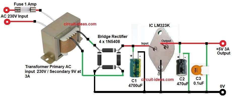
This 5V 3A Linear Power Supply Circuit is very simple for one to give it a try.

It uses only LM323K IC and few more parts which are easily available.

It gives 5V fixed output and can handle load up to 3A.

Circuit Working:

5V 3A Linear Power Supply Circuit Diagram

Parts List:

ComponentSpecificationQuantity
CapacitorsElectrolytic 4700uF 25V, 470uF 25V1 each
Ceramic 0.1uF1
SemiconductorsVoltage Regulator IC LM323K (5V 3A)1
Bridge Rectifier 1N5408 3A each 200V1
Transformer Primary AC input 230V / Secondary 9V at 3A1
Fuse 1 Amp1

The circuit have few parts.

Transformer change AC main voltage 230V to AC 9V.

Bridge diode change AC to DC.

Capacitor C1 make DC smooth.

IC LM323K give steady 5V output.

IC also protect from short circuit, overcurrent and overheating.

How to Build:

To build a 5V 3A Linear Power Supply Circuit follow the below steps:

  • Collect all parts as shown in circuit diagram.
  • Input pin goes to bridge +.
  • Ground pin goes 0V.
  • Output pin goes 5V 3A line.
  • Feed DC to pin1 goes with big capacitor C1.
  • Pin 2 join C2 and C3 capacitors.
  • Bridge one end goes ground.
  • Other 2 bridge pins go transformer secondary.
  • Transformer primary end go to AC input with fuse.

Conclusion:

This circuit is simple and reliable.

It give stable 5V for many electronic projects.

Parts are easy to find and cheap.

Good for hobby, testing bench and small microprocessor systems.

References:

Make 5v 3A dc power supply

Filed Under: Power Supply Circuits

About Admin-Lavi

Lavi is a B.Tech electronics engineer with a passion for designing new electronic circuits. Do you have questions regarding the circuit diagrams presented on this blog? Feel free to comment and solve your queries with quick replies

Previous Post: « 555 Pulse Generator Li-ion Battery Charger Circuit
Next Post: Simple IC L7660 Dual Power Generator Circuit »

Reader Interactions

Leave a Reply Cancel reply

Your email address will not be published. Required fields are marked *

Primary Sidebar


Categories

  • Alarm Circuits (45)
  • Amplifier Circuits (67)
  • Arduino Projects (99)
  • Audio Circuits (114)
  • Automobile Circuits (19)
  • Battery Charger Circuits (65)
  • Free Energy (13)
  • Heater and Temperature Controllers (13)
  • High Voltage (1)
  • Indicator Circuits (45)
  • Inverter Circuits (20)
  • IoT projects (1)
  • LDR Circuits (26)
  • LED and Lamps (148)
  • Meters and Testers (30)
  • Motor Controllers (22)
  • Oscillator Circuits (39)
  • Power Supply Circuits (104)
  • Remote Control Circuits (10)
  • Security and Protection (29)
  • Sensors and Detectors (126)
  • Solar Circuits (29)
  • Timer Circuits (41)
  • Transistor Circuits (87)
  • Transmitter Circuit (17)
  • Tutorials (8)
  • Water Level Controller (6)

Recent Posts

  • 12V Battery Low Voltage Alarm Circuit
  • Low Voltage Alert Circuit for 9V Battery
  • Digital Code Lock Circuit using IC 4017
  • Darkness Activated LED Circuit
  • Fan Start 10 Second Delay Timer Circuit

Recent Comments

  1. TDHofstetter on DIY Variable Power Supply Circuit using Arduino
  2. feathbuff on Simple Micro Ampere Meter Circuit
  3. Admin-Lavi on Simple School Project Multimeter Circuit
  4. choke on Simple School Project Multimeter Circuit
  5. Admin-Lavi on Analog to Digital Converter Circuit using IC 555

Copyright © 2026 | New Circuit Ideas