• Skip to primary navigation
  • Skip to main content
  • Skip to primary sidebar

Circuit Ideas for You

Get free circuit ideas online.

  • Home
  • Privacy Policy
  • About
Home » Low Impedance Driver Circuit using BJT Transistor

Low Impedance Driver Circuit using BJT Transistor

Last updated on 24 April 2026 by Admin-Lavi Leave a Comment

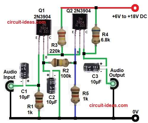
To begin with, this circuit shows a small audio amplifier which uses two BJT NPN transistors, they works with low impedance output like small speaker or earphone.

Also, the circuit takes weak input signal and makes it stronger and runs on DC supply from +6V to +18V, as the circuit is simple, low cost and easy to build.

Circuit Working:

Low Impedance Driver Circuit Diagram using BJT Transistor

Parts List:

ComponentsValuesQuantity
Resistors (All resistors are 1/4 watt)1k2
100k, 220k, 6.8k1
CapacitorsElectrolytic 10µF 25V3
Transistors 2N3904 NPN2
Power Supply DC +6V to +18V1

First, input signal comes through capacitor C1 and this C1 blocks DC and allows only AC signal, then signal goes to base of transistor Q1 and Q1 works as first amplifier stage which increases small signal.

Next, signal goes from Q1 to Q2 and this Q2 gives more amplification and also drives output load, so Q2 acts like driver stage.

Resistors R3 and R4 give bias to transistors and they set proper working point, resistors R1 and R5 connect to ground and control current flow.

Capacitor C2 stabilizes signal and reduces noise and capacitor C3 connects output and blocks DC from reaching the load.

Finally, amplified signal comes at output and we can connect small speaker here.

How to Build:

To build a Low Impedance Driver Circuit using BJT Transistor follow the below connection steps:

  • First, gather all the circuit parts as in diagram above.
  • Next, take transistor Q1 2N3904 and connect emitter to ground through resistor R1.
  • Then base of Q1 also goes to ground through capacitor C1.
  • After that connect collector pin Connect to positive supply through resistor R3 resistor.
  • Next, take transistor Q2 and connect emitter pin to ground through resistor R5.
  • Then base pin of Q2 connect between collector of transistor Q1 and resistor R3.
  • After that, connect collector pin to positive supply through resistor R4.
  • Next, take capacitor C1 and connect negative end to audio input and positive end between emitter of Q1 and resistor R1.
  • Then take capacitor C2 and connect positive end between base of Q1 and resistor R2 one end and negative of C2 goes to ground.
  • Lastly, capacitor C3 positive end connect between collector of Q2 and resistor R4 and negative end connect to audio output.

Conclusion:

Overall, this Low Impedance Driver Circuit using BJT Transistor gives simple and useful audio amplification which uses only two transistors and few components.

Hence, it works good for low impedance loads and is easy to build and test, also beginners can use this circuit for learning transistor amplifier basics.

References:

Datasheet BJT 2N3904

Filed Under: Amplifier Circuits, Audio Circuits, DIY Projects, Transistor Circuits

About Admin-Lavi

Lavi is a B.Tech electronics engineer with a passion for designing new electronic circuits. Do you have questions regarding the circuit diagrams presented on this blog? Feel free to comment and solve your queries with quick replies

Previous Post: « How to Replace IC TDA2050 with LM1875 IC in Audio Amplifier Circuit
Next Post: Transformerless Audio Amplifier Circuit using Germanium Transistor »

Reader Interactions

Leave a Reply Cancel reply

Your email address will not be published. Required fields are marked *

Primary Sidebar


Categories

  • 555 Timer Projects (17)
  • Alarm Circuits (56)
  • Amplifier Circuits (73)
  • Arduino Projects (102)
  • Audio Circuits (136)
  • Automation Circuits (4)
  • Automobile Circuits (22)
  • Battery Charger Circuits (75)
  • DIY Projects (20)
  • Free Energy (13)
  • Heater and Temperature Controllers (20)
  • High Voltage (11)
  • Hobby Circuits (2)
  • Indicator Circuits (56)
  • Inverter Circuits (19)
  • IoT projects (1)
  • LDR Circuits (34)
  • LED and Lamps (173)
  • Meters and Testers (35)
  • Motor Controllers (22)
  • Oscillator Circuits (44)
  • Power Supply Circuits (173)
  • Remote Control Circuits (9)
  • Security and Protection (41)
  • Sensors and Detectors (154)
  • Solar Circuits (31)
  • Timer Circuits (48)
  • Transistor Circuits (130)
  • Transmitter Circuit (17)
  • Tutorials (8)
  • Voltage Regulator (1)
  • Water Level Controller (7)

Recent Posts

  • UJT Based High Voltage Mini Audio Amplifier Circuit
  • Transformerless Audio Amplifier Circuit using Germanium Transistor
  • Low Impedance Driver Circuit using BJT Transistor
  • How to Replace IC TDA2050 with LM1875 IC in Audio Amplifier Circuit
  • Transistor Based Audio Amplifier Circuit

Recent Comments

  1. angel on 12 Watts Amplifier Circuit using Transistors
  2. Simple 1.5V Single Cell LED Flasher Circuit - Circuit Ideas for You on Simple 1.5V White LED Flasher Circuit
  3. Peter nichol Pilgrim on Simple Mobile Phone Signal Jammer Circuit
  4. Admin-Lavi on Simple Morse Key Circuit using IC 555
  5. Vladimír Zoch on Simple Morse Key Circuit using IC 555

Copyright © 2026 | New Circuit Ideas