This Multi-Purpose Audio Preamplifier Circuit using IC TL072 is a simple and useful audio amplifier circuit; also, we can use this circuit for microphone signals, AUX audio signals, guitar pickups, music players and other low-level audio sources.
Furthermore, the circuit increases weak audio signals to higher level output signals and therefore, the output can drive a power amplifier easily.
The circuit uses the TL072 dual JFET-input operational amplifier IC and this IC provides high input impedance and good audio performance.
Also the circuit uses a rotary switch to select different gain levels, so, the users can use different audio input levels without distortion.
Moreover, the circuit works with dual power supply voltage such as +12V and -12V and because of this, the amplifier gives better audio swing and clean sound output.
Circuit Working:
Parts List:
| Components | Values | Quantity |
|---|---|---|
| Resistors | 68k, 1k, 20k, 10k, 5k, 2k | 1 each |
| Capacitors | Electrolytic 1µF 25V, 10µF 25V | 1 each |
| Semiconductors | Integrated Circuit TL072 | 1 |
| Rotary Selector Switch | 1 | |
| Dual Power Supply ±12V | 1 |
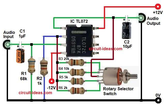
First, the audio input signal enters the circuit through capacitor C1 and this capacitor blocks unwanted DC voltage and passes only AC audio signal.
Then, resistor R1 provides bias reference to the non-inverting input of the op-amp.
Next, the filtered audio signal goes to pin 3 of the TL072 IC and this IC works in non-inverting amplifier mode;
Hence, the output signal stays in phase with the input signal.
After that, the amplifier gain depends on resistor R2 and selected feedback resistor R3, R4, R5 and R6. T
The rotary switch S1 selects only one resistor at a time and as a result, the circuit changes gain according to the input signal level.
For example:
- Microphone signals need high gain
- AUX signals need medium gain
- Guitar pickups need high input impedance
- Strong audio signals need low gain
Then, the amplified signal comes out from pin 1 of the IC and capacitor C2 removes DC voltage from the output stage and sends clean audio output to the next amplifier stage.
How to Build:
To build a Multi-Purpose Audio Preamplifier Circuit using IC TL072 follow the below connection steps:
- Start, by collecting all circuit components as shown in circuit diagram above.
- Next, take IC TL072 pin 1 and this pin is output pin of first op-amp section, also the amplified audio signal comes from this pin and capacitor C2 connects to this pin for output coupling.
- Then, take pin 2 which is the is inverting input pin and resistor R2 connects between pin 2 and ground.
- Also feedback resistors R3, R4, R5 and R6 connect to this pin through rotary switch S1.
- After that, take pin 3 which is the non-inverting input pin; the audio input signal enters this pin through capacitor C1 and also resistor R1 connects from pin 3 to ground.
- Next, take pin 4 and this pin is -Vcc pin and connects to negative power supply voltage (-12V).
- Lastly, take pin 8 and this pin is +VCC pin and connects to positive power supply voltage (+12V).
Conclusion:
Overall, this Multi-Purpose Audio Preamplifier Circuit using IC TL072 is a simple and effective audio amplifier circuit.
The circuit increases weak audio signals and provides clean output sound and also, the rotary switch allows easy gain selection for different input signal levels.
Moreover, the TL072 IC provides high input impedance and stable audio performance.
Therefore, beginners and hobbyists can build this circuit easily for many audio applications.
Leave a Reply