LM386 is a very popular low voltage audio amplifier IC, many hobby users like this IC because it needs only few external parts and it gives good sound output for small speaker projects.
In this Easy DIY LM386 Audio Amplifier Circuit, we explain two simple amplifier circuits using LM386 IC, the first circuit gives around 20 times voltage gain and the second circuit gives around 200 times voltage gain by using extra capacitor between pin 1 and pin 8.
Also, these circuits work well for small audio projects, radio audio booster, microphone amplifier, portable speaker and learning electronics experiments.
Furthermore, both circuits use 8 ohm speaker and low DC supply from 4V to 12V.
About LM386 IC:
LM386 is a low power audio amplifier IC and it can run from battery supply and it does not need dual power supply.
Also, the IC gives voltage gain from 20 to 200, as its internal gain stays at 20 by default; but when we connect capacitor between pin 1 and pin 8, the gain increases to 200.
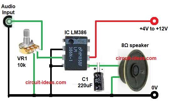
Circuit Working for 20 times voltage gain:
Parts List:
| Components | Values | Quantity |
|---|---|---|
| Variable resistor | Potentiometer 10k | 1 |
| Capacitor | Electrolytic 220uF 25V | 1 |
| Semiconductors | LM386 Audio Amplifier IC | 1 |
| 8Ω Speaker | 1 | |
| Power Supply +4V to +12V DC | 1 |
In this circuit, LM386 works as audio power amplifier, the audio input signal enters through VR1 variable resistor; then this variable resistor controls input volume level.
After that, pin 3 receives audio input signal and pin 2 connects to ground.
Moreover, the IC amplifies the weak audio signal internally and since pin 1 and pin 8 stay open, the voltage gain remains 20.
Pin 5 sends amplified output signal to speaker through C1 capacitor and this capacitor blocks DC voltage and passes only audio signal to speaker.
Hence, the speaker converts amplified electrical signal into sound; and lastly, the circuit works with battery supply from 4V to 12V.
How to build a 20 Times Voltage Gain Audio Amplifier Circuit:
To build a 20 times voltage gain audio amplifier circuit follow the below connection steps:
- Start, by gathering all the parts as in circuit diagram above.
- First, place LM386 IC carefully on breadboard or PCB.
- Next, Connect pin 2 to ground.
- After that, Connect pin 3 to input signal through VR1 variable resistor.
- Then connect pin 4 directly to ground line.
- Now connect 220uF capacitor positive terminal to pin 5 and connect speaker between capacitor output and ground.
- Lastly, connect pin 6 to positive DC supply from +4V to +12V.
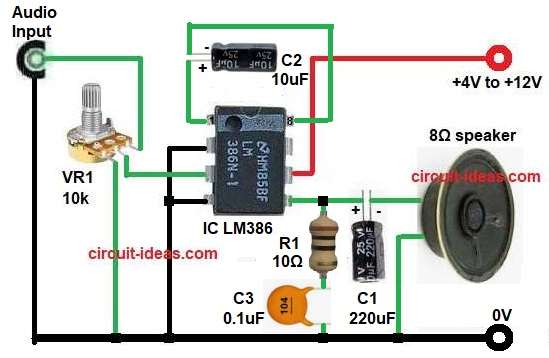
Circuit Working for 200 Times Voltage Gain:
Parts List:
| Components | Values | Quantity |
|---|---|---|
| Resistors | 10Ω | 1 |
| Potentiometer 10k | 1 | |
| Capacitor | Electrolytic 220uF 25V, 10uF 25V | 1 each |
| Ceramic 0.1uF | 1 | |
| Semiconductors | LM386 Audio Amplifier IC | 1 |
| 8Ω Speaker | 1 | |
| Power Supply +4V to +12V DC | 1 |
This circuit works almost same as X20 amplifier circuit, but here one extra capacitor connects between pin 1 and pin 8 and this 10uF capacitor increases voltage gain from 20 to 200.
Hence, the circuit produces much louder sound output compared to first circuit.
Also, the R1 resistor and C3 capacitor form Zobel network and this network improves circuit stability and reduces unwanted oscillation noise.
Finally, the output signal goes through C1 capacitor to 8 ohm speaker and this speaker gives louder and clearer sound.
How to Build 200 Times Voltage Gain Audio Amplifier Circuit:
To build a 200 times voltage gain audio amplifier circuit follow the below connection steps:
- Start, by gathering all the parts as in circuit diagram above.
- First, place LM386 IC carefully on breadboard or PCB.
- Next, connect C2 capacitor between pin 1 and pin 8, in which positive side goes to pin 1.
- Now connect pin 2 to ground.
- After that, connect pin 3 to input signal through VR1 variable resistor.
- Then connect pin 4 directly to ground line.
- Now connect 220uF capacitor positive terminal to pin 5 and connect speaker between capacitor output and ground.
- Also, connect R1 resistor in series with C3 capacitor from pin 5 to ground.
- Lastly, connect pin 6 to positive DC supply from +4V to +12V.
Testing the Circuit
- Connect power supply correctly.
- Connect audio input from mobile or audio source.
- Rotate variable resistor slowly.
- Listen sound from speaker.
- Increase volume carefully to avoid distortion.
Conclusion:
Overall, LM386 amplifier circuits give simple and low cost solution for small audio amplification projects.
The X20 circuit gives stable normal sound amplification with minimum components and the X200 circuit gives much higher gain and louder sound output by adding capacitor between pin 1 and pin 8.
Therefore, both circuits are easy for beginners and hobby users, as this project for Easy DIY LM386 Audio Amplifier Circuit help students learn audio amplification and practical electronics in simple way.
Leave a Reply