A step-up DC converter is a useful electronic circuit that increases a low DC input voltage into a higher DC output voltage.
In this circuit, the TDA2004 IC works as the main switching and amplification device, although this IC is mainly designed as an audio amplifier, we can also use it for DC voltage boosting applications, specifically for simple, low-power step-up converters, such as converting 12V to 24V.
In this design, the circuit takes low DC voltage at the input side and converts it into higher DC voltage at the output side.
Therefore, this DC Step-Up Converter Circuit using Audio Amplifier IC becomes useful for battery-operated projects, portable power supplies, car electronics and small inverter applications and also, the circuit uses simple external components, so it is easy to build.
Circuit Working:
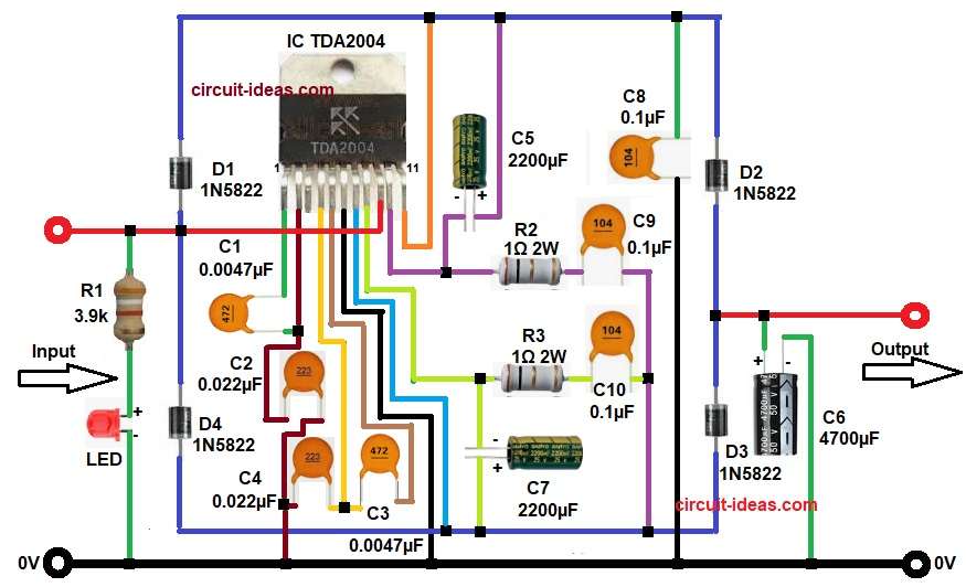
Parts List:
| Components | Values | Quantity |
|---|---|---|
| Resistors | 3.9k 1/4 watt | 1 |
| 1Ω 2W | 2 | |
| Ceramic 0.0047µF, 0.022µF | 2 each | |
| Ceramic 0.1µF | 3 | |
| Electrolytic 2200µF 25V | 2 | |
| Electrolytic 4700µF 50V | 1 | |
| Diode 1N5822 | 4 | |
| Main step-up converter IC TDA2004 | 1 | |
| Any standard LED | 1 |
At first, the DC input supply enters the circuit with diode D1 and diode D4 help control current direction and they also give circuit protection.
After that, the TDA2004 IC starts work as oscillator and power driver stage as the IC has two internal amplifier sections and both sections work together and they generate switching pulses.
Capacitors C1, C2, C3 and C4 help set the frequency and they also help signal coupling between both amplifier stages.
Next, the outputs from pin 10 and pin 8 pass through resistors R2 and R3 as these resistors limit the current and they also protect the output section.
After this, capacitors C9 and C10 smooth the fast switching pulses and meanwhile, capacitors C5 and C7 store energy and they also stabilize the supply voltage.
Then diodes D2 and D3 rectify the voltage. and they send boosted voltage to output capacitor C6.
Finally, capacitor C6 stores the boosted DC voltage. and it gives smooth higher DC output.
So, the circuit converts low DC voltage into higher DC voltage.
How to Build:
To build a DC Step-Up Converter Circuit using Audio Amplifier IC following steps are required for connection:
- Start, the circuit by collecting all components as shown in the diagram above.
- Next, start with IC TDA2004 with pin 1 connects to one end of capacitor C1 and other end of C1 connects to pin 2 of the IC.
- After that, take pin 2 connects to one end of capacitor C2 and other end of C2 goes to pin 4 of the IC.
- Then pin 4 connects to one end of capacitor C3 and it also connects to one end of capacitor C4 and the other end of C4 goes to ground.
- Then again take pin 5 connects to capacitor C3.
- After that take pin 6 goes to ground 0V.
- Then take pin 7 connects between capacitor C7 positive terminal and diode D4 cathode.
- Again take pin 8 which is output pin of second amplifier section and it connects to capacitor C7 negative terminal and it also connects to resistor R3 and capacitor C10.
- After that take pin 9 connects to diode D1 anode and it also connects to diode D4 anode and this pin also goes to input DC supply.
- Then take pin 10 is first amplifier output pin which connects to resistor R2 and capacitor C9 and it also connects to one end of capacitor C5 negative.
- Then pin 11 connects to positive voltage line and it connects between diode D1 cathode and capacitor C5 positive.
- After that take resistor R1 and LED and connect both in series from positive input line to ground.
- After that, again connect diodes D2 and D3 in output positive line.
- Next, connect capacitor C8 between capacitor C5 positive and diode D2 anode.
- Lastly, connect capacitor C6 between positive output line and ground.
Conclusion:
DC Step-Up Converter Circuit using Audio Amplifier IC s a simple and effective voltage booster design which increases low DC voltage into higher DC output by using switching action and capacitor-diode filtering stages.
Moreover, the circuit uses low-cost components and easy pin connections so it is suitable for DIY electronics projects and power supply applications.
Because of simple construction and stable output this circuit is a good choice for beginners and hobby users, also we can use it in battery backup systems, car gadgets and portable voltage boosting projects.
Leave a Reply