The IC 555 generates an electric current at a set frequency for healing in this Simple Hulda Clark Zapper circuit, also Hulda Clark developed this type of circuit, known as a Hulda Clark zapper, in 2003.
Circuit Working:
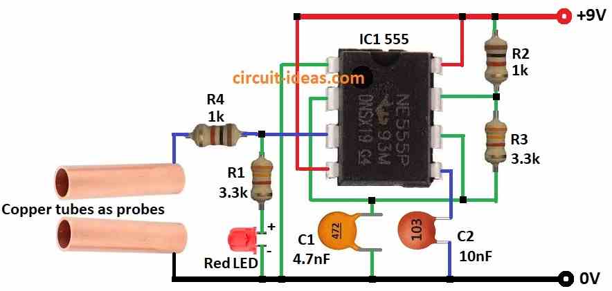
Parts List:
| Components | Values | Quantity |
|---|---|---|
| Resistors | 1k, 3.3k 1/4 watt | 2 each |
| Capacitors | Ceramic 4.7nF | 1 |
| Ceramic 10nF | 1 | |
| Semiconductors | IC 555 | 1 |
| LED Red 5mm 20mA | 1 | |
| Copper tubes as probes | 2 |
Many doctors say Hulda Clarks zapper claims are not true, also there is no science proof that zapper can heal or cure sickness.
So using zapper can or may be unsafe and cause health problems, but if still anyone want to try the circuit here is how it works:
Firstly, the circuit uses 9V battery to power it and IC 555 works as astable multivibrator which means it gives square wave output again and again.
Furthermore, parts like capacitor C1 and resistor R2 decide the signal frequency with around tens of kHz.
Capacitor C2 and resistor R3 help remove glitches means debounce in the signal and resistor R1 and red LED show power is ON.
Copper tubes act like electrodes and when user holds them the square wave signal goes into the body.
Important:
Always talk to doctor before using zapper it can be risky and science does not support its healing claims.
Formulas:
We use IC 555 to make an astable multivibrator for Hulda Clark Zapper, goal is to get square wave with correct frequency and duty cycle.
Formula for Frequency (f):
f = 1.44 / (R1 + 2×R2) × C
- R1 and R2 are resistors
- C is timing capacitor
Duty Cycle D:
D = R2 / (R1 + 2×R2)
Shows how long output stays ON compared to OF and to get right frequency and duty cycle we need change R1, R2 and C values.
Reminder: Always be careful with electronic therapy and check proper safety rules before using it.
How to Build:
To build a Simple Hulda Clark Zapper Circuit follow the below mentioned steps for connections:
- First, connect pin 1 of IC 555 to ground.
- Next, connect pin 2 to pin 6 of IC 555.
- After that, connect capacitor C1 between pin 2 & 6 and ground.
- Then connect pin 3 output to one copper tube through resistor R4 and connect the other copper tube to ground; also from pin 3 connect a resistor R1 and red LED in series to ground to show power status.
- Now connect pin 4 to positive supply of 9V and also connect pin 8 to positive supply of 9V.
- Also, connect pin 5 to capacitor C2 and the other side of C2 to ground and place resistor R3 between pin 6 and pin 7.
- Connect resistor R2 from pin 7 to positive supply of 9V.
Important Note:
- As said before there is no scientific proof that zappers can heal or treat diseases, also doctors and medical experts warn against using zappers because they may cause health problems.
- Always talk to a doctor before trying or using any zapper circuit.
Conclusion:
We can build a easy and Simple Hulda Clark Zapper Circuit using IC 555, But remember there is no real evidence of health benefits.
Due to safety risks medical authorities recommend not using these devices, But if anyone is thinking about using a zapper then see a doctor first.
Hi, Would anything change is I use a MC1455 chip? Is there any difference between either the 555 or 1455?
Thanks
Hi,
There is no big change using MC1455, as MC1455 and 555 are almost the same. MC1455 is just CMOS version of 555 timer.
Difference is:
MC1455 uses less power and battery last longer, it makes less heat and its pin numbers and connection are the same of IC 555.
For your Hulda Clark Zapper circuit, it will work the same and Frequency will be almost be the same and there is no need to change resistor or capacitor.
So yes, you can replace 555 with MC1455 directly. Best of luck👍.
Thanks