This tutorial teaches us about Battery Level Indicator Circuit using IC MN13811
It shows when battery is low and indicates us to recharge.
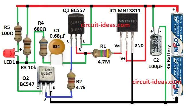
Use MN13811 IC and 2 transistors as they work together to turn ON the LED when battery is low.
The circuit is good for small 3V battery devices.
It is for very low power use like 1µA when idle and 20µA when LED blinks.
Circuit Working:
Parts List:
| Component | Quantity |
| Resistors (All resistors are 1/4 watt unless specified) | |
| 4.7M | 1 |
| 4.7k | 1 |
| 10k | 1 |
| 680Ω | 1 |
| 100Ω | 1 |
| Capacitors | |
| Ceramic 0.68µF | 1 |
| Electrolytic 100µF 25V | 1 |
| Semiconductors | |
| IC MN13811 | 1 |
| Transistor BC557 | 1 |
| Transistor BC547 | 1 |
| LED Any 5mm 20mA | 1 |
| Battery 3V | 1 |
This MN13811 IC checks battery health.
It watches battery voltage and if voltage drops too low then it sends signal.
Pin 2 (V+) is where voltage is checked.
If battery is OK at voltage high then output is low and transistors stay OFF.
If battery is low at voltage drops then pin 1 gives high signal.
This turns ON the transistors Q1 BC557 and Q2 BC547.
Transistor Q2 gets ON, LED1 lights up by indicating battery is low, that means it time to charge or change.
Formulas with Calculations:
MN13811G IC works at set voltage to around 2.9V to 3.0V.
Cutoff voltage set by resistors R1 and R2.
Threshold Voltage Formula:
V_threshold = V_battery × (R2 / (R1 + R2))
where,
- V_battery is 3V
- R1 is 4.7M
- R2 is 4.7k
Calculation:
V_threshold = 3V × (4700 / (4,700,000 + 4700))
= 3V × 0.000999
= 2.997V means 3V
So circuit turns ON when voltage drops near 3V.
LED Current Formula:
I_LED = (V_supply – V_LED) / R5
where,
- V_supply is 3V
- V_LED is 1.8V
- R5 is 100Ω
Calculation:
I_LED = (3V – 1.8V) / 100Ω
= 1.2V / 100Ω
= 12mA
LED gets enough brightness and not too much power is used.
How to Build:
To build a Battery Level Indicator Circuit using IC MN13811 follow the below mentioned steps:
- Put all parts like in circuit diagram.
- Connect 3V battery positive to pin 2 (V+) of MN13811 IC.
- Connect pin 3 of IC to battery negative GND.
- Add 100uF capacitor C2 across power that makes voltage stable.
- Connect 4.7M resistor R1 from pin 1 of IC to base of Q1 BC557.
- Put 0.68uF capacitor C1 to pin 1 of IC.
- Connect collector of Q1 to base of Q2 BC547 using 4.7k resistor R2.
- Emitter of Q1 goes to positive supply.
- Collector of Q2 goes to GND.
- Connect LED1 positive to 100Ω resistor R5 to collector of Q2.
- Add resistor R3 from positive rail to point between R4 and LED1.
- Put R4 between C1 and R3.
Conclusion:
This Battery Level Indicator Circuit using IC MN13811 shows low battery with LED.
MN13811 IC checks battery level.
Transistors works like switch to turn LED ON.
It is good for battery devices to watch power level.
Leave a Reply