Intercom system is device for talking at short distance; so a 9V Battery Powered Transistor Intercom Circuit uses 9V battery which is good for home or office talk.
Also, it uses only transistors which is easy to understand and works well.
Furthermore, the circuit has mic and small speaker as sound and a BC547 transistors make sound loud and 2N2222 transistor help speaker work right.
Circuit Working:
Parts List:
| Components | Values | Quantity |
|---|---|---|
| Resistors (All resistors are 1/4 watt unless specified) | 10k | 2 |
| 1M | 1 | |
| 220k | 1 | |
| 2.2k | 1 | |
| 100k | 1 | |
| 150Ω | 1 | |
| Capacitors | Ceramic 0.1µF | 3 |
| Electrolytic 10µF 25V | 2 | |
| Electrolytic 100µF 25V | 1 | |
| Semiconductors | Transistors BC547 | 2 |
| Transistor 2N2222 | 1 | |
| Electret Microphone | 1 | |
| Push-to-ON Switch | 1 | |
| Slide Switch | 1 |
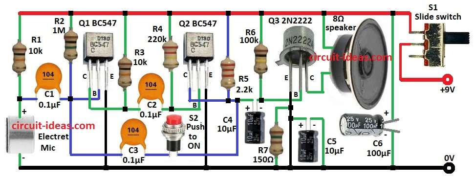
Circuit start with electret mic which catches sound around and this sound is weak so it needs to get boost first.
Then resistor R1 and capacitor C1 clean and steady mic signal and after that, transistor Q1 make signal stronger with preamplifier.
Now R2 gives bias, R3 keep it stable then signal go through C2 to next stage and second transistor Q2 boost signal more.
R4 and R5 set the gain, while C3 smooths the signal, then the final stage uses transistor Q3 as a power amplifier that drives an 8-ohm speaker.
R6, R7 are for bias and current control and C4, C5, C6 remove noise and keep circuit clean.
The circuit runs on a 9V battery, so S1 acts as the power switch and S2 works as a push-to-talk button when the user presses it to speak.
Note:
- To make 2 way intercom build 2 same circuits.
- Connect them as shown in diagram.
- Standby current is about 20mA.
Formulas with Calculations:
Formula for voltage gain:
Voltage gain (Av) = RC / RE
First stage Q1:
RC is 10k
RE is 1k
Av1 is 10k / 1k = 10
Second stage Q2:
RC is 2.2k
RE is 220Ω
Av2 is 2.2k / 220 = 10
Total gain:
A_total = 10 × 10 = 100
Speaker Power:
Power (P) = V² / R
V is 6V (RMS) and R is 8Ω
P = 6² / 8 = 36 / 8 = 4.5W
Hence, speaker gets around 4.5 watts of power.
How to Build:
To build a 9V Battery Powered Transistor Intercom Circuit follow below steps for connection:
- First, connect electret mic in series with resistor R1
- Next, one end go to +9V other end go to GND
- Then connect one side of capacitor C1 between mic and R1 junction and then connect other side of C1 go to base of transistor Q1
- Now connect one end of resistor R2 to +9 and other end connects to base of Q1
- Also, connect one end of resistor R3 to +9V and other end go to collector of Q1 and emitter of Q1 to GND
- Further, connect one side of capacitor C2 to collector of Q1 and other side go to base of transistor Q2
- After that, connect one end of resistor R4 to +9V and other end go to base of Q2
- Then connect one end of resistor R5 to +9V and other end go to collector of Q2 and emitter of Q2 go to GND
- Positive side of capacitor C4 go to resistor R5 at Q2 collector and negative side of C4 go to resistor R6 and other end of R6 goes to base of transistor Q3
- Next, connect C3 and S2 in series, with one end go to base of Q1 and other end go to positive side of C4
- Also, emitter of Q3 goes to GND and then connect both between emitter of Q3 and GND
- One end of 8Ω speaker go to collector of Q3 and other end of speaker go to +9V
- Now positive of capacitor C6 go to +9V and negative of C6 go to GND
- Finally, connect one side of S1 to +9V battery terminal and other side of S1 go to main +9V rail of circuit
Conclusion:
Overall, this 9V Battery Powered Transistor Intercom Circuit is cheap and good for short-range talk., as it uses basic parts but gives clear sound.
Also, we can upgrade it and make it louder or can add volume control.
Tank and helpful