An electronic adjustable thermostat controls temperature in heating or cooling systems, as this adjustable thermostat circuit uses the low-power IC LM56 chip to switch between two temperature modes.
First, it controls outside transistor for output load and then IC LM56 give reliable, precise temperature control.
Moreover, it is good for many uses like check temperature and stop overheating, as temperature limit changes easy with variable resistor so circuit work in many jobs.
Also, circuit runs on 5V DC power.
Circuit Working:
Parts List:
| Components | Values | Quantity |
|---|---|---|
| Resistors (All resistors are 1/4 watt unless specified) | 100k | 1 |
| 47k | 2 | |
| Preset 10k | 1 | |
| Preset 50k | 1 | |
| Preset 100k | 1 | |
| Semiconductors | IC LM56 | 1 |
| Transistor PNP BC557 | 1 | |
| Transistor NPN BC547 | 1 | |
| Rectifier Diode 1N4007 | 2 | |
| Relay 5V | 2 |
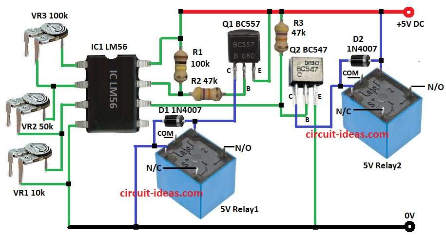
Circuit work by LM56 chip which read temperature and compare with user set levels and also user can change levels anytime.
Furthermore, IC LM56 has two comparators VT1, VT2 which compare temperature to reference, so use presets VR1, VR2 and VR3 instead of fixed resistors.
VR1 10k lowers the threshold to VT1, VR2 50k is middle and VR3 100k is upper threshold of VT2 and they act like voltage divider to set switch points.
Then if temperature goes above set point then LM56 change outputs Out1 and Out2.
Out1 goes to PNP BC557 driving relay L1 with diode D1 for back-EMF protection and Out2 goes to NPN BC547 driving relay/load L2 with diode D2 for back-EMF protection.
Also, when the temperature rises above the upper threshold then relay1 turns ON to start cooling and when it falls below the lower threshold then relay2 turns ON to start heating.
Hence, adjust VR1, VR2, VR3 to change ON/OFF temp without changing the resistors.
Formulas with Calculations:
In the LM56 thermostat circuit, VR1 (10k), VR2 (50k) and VR3 (100k) voltage dividers set the temperature switching points.
We can calculate the lower threshold VT1 as:
Formula:
Vref: =2.7V = Vref × ( VR2 / (VR1 + VR2 + VR3) )
Given:
Vref = 2.7 V; VR1 = 10 kΩ; VR2 = 50 kΩ; VR3 = 100 kΩ. Sum = 10 + 50 + 100 = 160 kΩ.
Lower Threshold (VT1):
VT1 = 2.7 × (50 / 160) = 2.7 × 0.3125 = 0.84375 V = 0.84 V
Upper Threshold (VT2):
= Vref × ( (VR2 + VR3) / (VR1 + VR2 + VR3) )
VT2 = 2.7 × (150 / 160) = 2.7 × 0.9375 = 2.53125 V = 2.53 V
For Q1 PNP BC557 base current is:
( Vout1 – VBE ) / VR2
IB = (Vout1 − VBE) / VR2 = (5.0 − 0.7) / 50,000 = 4.3 / 50,000 = 0.000086 A = 0.086 mA
For Q2 (NPN BC547) with β=100 collector current is:
β × IB
IC = β × IB = 100 × 0.000086 = 0.0086 A = 8.6 mA
Relay coil current (Irelay):
Irelay = (Vsupply − VCEsat) / Rcoil
= (5.0 − 0.2) / 200 = 4.8 / 200 = 0.024 A = 24 mA
How to Build:
To build a Adjustable Thermostat Circuit using IC LM56 follow below steps:
- First, assemble all the required components mentioned in the above circuit diagram
- Next, connect pin 1 of IC1 LM56 to center leg of VR1 and second leg of VR1 connect to pin 2 of IC1
- After that, connect pin 2 of IC1 LM56 to center leg of VR2 and second leg of VR2 connect to pin 3 of IC1
- Now connect pin 3 of IC1 LM56 to center leg of VR3 and second leg of VR3 connect to pin 4 of IC1 and GND
- Then, connect pin 6 of IC1 to base of transistor Q and connect a resistor R3 from base of transistor Q2 and positive supply of the circuit.
- Also, connect resistor R1 between pin 7 and pin 8 of IC1 and positive supply and then connect resistor R2 from pin 7 to base of transistor Q1.
- Next, connect the emitter of transistor Q1 to positive supply and then connect the collector of transistor Q1 to coil pin of relay1 .
- Further, connect diode D1 from coil pin of realy1 to other coil pin of relay1.
- Now connect emitter of transistor Q2 to GND of the circuit and then connect the collector of transistor Q2 to coil pin of relay2
- Finally, connect a diode D2 from coil relay2 pin to positive supply.
Conclusion:
To conclude, this Adjustable Thermostat Circuit using IC LM56 control temperature with smart and reliable way, also user can set different temperature limit with variable resistors.
Therefore, with transistor and relay the circuit can handle more current and is good for actual heating and cooling work.
Leave a Reply