This Arduino Based Motion Dog Barking Alarm Circuit make dog sound when motion detects.
it uses Arduino Nano, Pir sensor, Dog Sound Module, BC547 transistor, IC LM386 Amplifier Module and 8Ω Speaker.
Pir senses human or animal move.
Arduino play dog bark sound to scare intruder.
This is simple and low cost security system.
Circuit Coding:
int pirPin = 2;    // PIR sensor connected to D2
int trigPin = 3;   // BC547 base connected from D3

void setup() {
  pinMode(pirPin, INPUT);
  pinMode(trigPin, OUTPUT);
  digitalWrite(trigPin, LOW);
}

void loop() {
  int motion = digitalRead(pirPin);

  if (motion == HIGH) {
    digitalWrite(trigPin, HIGH);   // trigger transistor ON
    delay(5000);                   // play sound for 5 sec
    digitalWrite(trigPin, LOW);    // stop sound
  }
  else {
    digitalWrite(trigPin, LOW);    // keep off when no motion
  }
}
Code Explanation:
- Pir sensor output connect to pin D2 of Arduino.
- when there is no motion then Pir is low.
- when motion detect then Pir is high.
- Arduino read this signal.
- if signal is high then Arduino send high to D3 pin.
- D3 go to base of BC547 transistor through 10k resistor.
- BC547 switch ON and connect play pin of dog sound module to GND.
- Through this it starts with dog sound playback.
- delay(5000) keep sound playing for 5 sec.
- after 5 sec the Arduino send low to D3, transistor goes OFF and sound stops.
- If Pir does not detect motion then D3 stays low and sound stay OFF.
Circuit Working:
Parts List:
| Component | Value | Quantity |
|---|---|---|
| Resistors | 10k 1/4 watt | 1 |
| Semiconductors | Arduino Nano | 1 |
| PIR Motion Sensor | 1 | |
| Dog Barking Sound Module | 1 | |
| IC LM386 Amplifier Module | 1 | |
| Speaker 8Ω from 0.25W to 2W | 1 |
Pir sensor watches the area.
when someone moves then Pir sensor output goes high.
Arduino read this from D2.
Arduino send high signal from D3 to Q1 BC547 transistor base.
BC547 switches ON and connects dog sound module to play pin to ground.
Dog sound module play dog bark sound.
Sound goes to LM386 amplifier module.
LM386 amplify sound and sends to speaker.
Speaker make loud bark noise.
After some time sound stops and circuit waits again.
Arduino is powered from USB or 5V pin.
Formulas and Calculations:
Following are the basic formula for Motion Dog Barking Alarm Circuit:
output power approx = (V^2) / (2 * Rload)
for 5V and 8ohm speaker power = (25)/(16) = 1.56W max theoretical
delay time in code = delay(ms) value
example:
- V is 5V
- Rload is 8 ohm
P = (5^2)/(2*8) = 25/16 = 1.56 watt approx
How to Build:
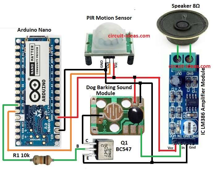
To build a Arduino Based Motion Dog Barking Alarm Circuit follow the below steps for connections:
- Gather all the parts as shown in circuit diagram
- Pir sensor Vcc to Arduino 5V
- Pir sensor GND pin connect to Arduino GND
- Pir sensor out pin connect to Arduino D2
- Dog sound module Vcc pin connect to 5V
- Dog sound module GND pin connect to Arduino GND
- Dog sound module play pin connect to BC547 collector pin of Q1 transistor
- BC547 base pin connect to Arduino D3 through 10k resistor
- BC547 emitter pin to GND
- LM386 module input pin connect from dog audio out pin.
- LM386 module GND pin connect to GND
- LM386 module Vcc pin connect to 5V
- Connect one end of 8 ohm speaker with the output connector of the LM386 amplifier module
Conclusion:
This project for Arduino Based Motion Dog Barking Alarm Circuit help to scare thief using fake dog bark.
It is a simple low cost alarm.
The circuit can be placed at door or garden.
It is an easy to build circuit for beginner.
Leave a Reply