This article is about small Audio Oscillator Organ Circuit, we can hold in our hand, as it plays simple notes and make funny tones; also it uses very simple parts and shows how oscillator make sound.
Further, circuit shows how amplifier make sound big and it also works on low voltage which is safe for kids and it gives a clear tone which we can tune tone very easily.
Circuit Working:
Parts List:
| Components | Values | Quantity |
|---|---|---|
| Resistors | 1k, 4.7k | 2 each |
| 10k, 22k, 470Ω | 1 each | |
| Potentiometer 50k | 1 | |
| Capacitors | Electrolytic 10uF, 3.3uF | 1 each |
| Ceramic 0.1uF, 0.05uF | 1 each | |
| Semiconductors | Transistors NPN BC547 | 2 |
| Transistor PNP BC557 | 1 | |
| Output Audio Transformer for small speaker | 1 | |
| 8Ω small speaker | 1 | |
| On Off switch | ||
| Power suuply 4.5V | 1 |
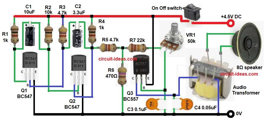
The circuit uses two NPN transistors Q1 and Q2 as multivibrator, and the capacitors and resistors connected to these NPN transistors make oscillation.
Then this oscillation creates audio frequency.
Further, the 10uF C1 and 3.3uF C2 capacitors decide speed of oscillation and the 10k R2 and 4.7k R3 resistors also shape the timing.
The output from the Q2 transistor goes to a PNP transistor Q3 and then this Q3 transistor works like small power amplifier; the amplified signal then goes through output audio transformer small speaker type.
Moreover, the 0.1uF C3 and 0.05uF C4 capacitors help smooth and filter sound and VR1 50k variable resistor changes the pitch; also when we rotate this VR1 potentiometer tone changes.
Formula:
Below formula shows how R and C decide the speed of oscillation and the tone comes from RC timing.
Frequency formula: f = 1 / (1.4 * R * C)
where,
- f is the frequency for the pitch of sound.
- R is the resistor value for 10k R2
- C is the capacitor value for 10uF C1
- 1.4 is the constant number comes from the way the multivibrator (the oscillator) works
How to Build:
To build a Audio Oscillator Organ Circuit follow the below steps for connection:
- First, place all parts same like circuit diagram.
- Next, connect Q1 emitter to ground, connect Q1 collector to R1 1k resistor and then to positive.
- Then connect C1 10uF capacitor from Q1 collector to Q2 base and connect Q2 emitter to ground and also connect Q2 collector to R4 1k resistor and then to positive.
- After that, connect C2 3.3uF capacitor from Q2 collector to Q1 base and connect R2 10k resistor from Q2 base to positive.
- Now connect R3 4.7k resistor from Q1 base to positive and then take output from Q2 collector through R5 4.7k, then to R7 22k resistor.
- Also, R7 22k resistor and VR1 pot, connect this line to Q3 base.
- Further, connect Q3 emitter to positive and connect Q3 collector to primary output audio transformer through capacitor C4.
- Next, connect transformer primary third pin to GND and connect both the secondary pins of audio transformer to 8ohm speaker.
- Place C3 0.1uF capacitor from Q3 base to ground and then place R6 470 ohm resistor from joint of R5 4.7k and R7 22k to ground.
- Finally, place VR1 50k pot between Q3 base and signal line for tone control and connect on off switch to 4.5V to positive power line.
Conclusion:
To conclude, this Audio Oscillator Organ Circuit is simple, as it needs few parts and makes organ like tones; also circuit is good for hobby learning and is easy to modify pitch and sound.
Additionally, it works safe on low voltage.

Leave a Reply