This circuit is for Automatic 12V Battery Charger Circuit with SCR Cutoff, first it charges the battery and then it stops charging when the battery becomes full.
Also, the circuit uses simple parts like transformer, diodes, SCR, resistor and capacitor and we can easily find these parts in market or online.
So, this circuit protects the battery from overcharging, because overcharging damages battery life and therefore this circuit becomes useful.
Circuit Working:
Parts List:
| Components | Values | Quantity |
|---|---|---|
| Resistors ( All resistors are 1/4 watt ) | 1.5k, 560Ω, 10k | 1 each |
| 2k | 2 | |
| Potentiometer 10k | 1 | |
| Capacitor | Electrolytic 100µF 25V | 1 |
| Any standard LED for charging & full indicator | 1 each | |
| Zener Diode 6.8V 1W | 1 | |
| Power SCR1 BT151, control SCR2 MCR100-6 | 1 each | |
| Diode 1N4002 | 1 | |
| Bridge Diodes 1N5402 | 4 | |
| Transformer 220V AC primary, secondary 0V-15V 3A | 1 | |
| Battery 12V lead-acid or similar | 1 |
First, 220V AC goes to step down transformer and it converts high voltage AC into low voltage AC around 15V.
Then diodes D1 to D4 make bridge rectifier and they convert AC into DC.
After that, this DC goes to battery through SCR1 and when battery voltage is low then SCR1 conducts and allows current to flow, so battery starts charging.
Meanwhile, LED1 shows charging condition and as battery charges the voltage across battery increases slowly.
Also, diode D5 gives gate trigger to SCR1 and blocks reverse current, so it protects SCR1.
At the same time, resistor R3 helps to sense battery voltage which sets cutoff level and also limits the current.
Now, control section works, where Zener diode ZD1 senses battery voltage and when battery voltage reaches around 13.5V to 14V then Zener starts conducting.
Then, SCR2 triggers and when SCR2 turns ON as it pulls gate current of SCR1 to ground, so SCR1 stops conducting.
As a result, charging stops and LED2 glows and shows battery is fully charged.
Finally, capacitor C1 and variable resistor VR1 adjust timing and sensitivity and through this user can set cut-off voltage using VR1.
How to Build:
To build a Automatic 12V Battery Charger Circuit with SCR Cutoff follow the below connection steps:
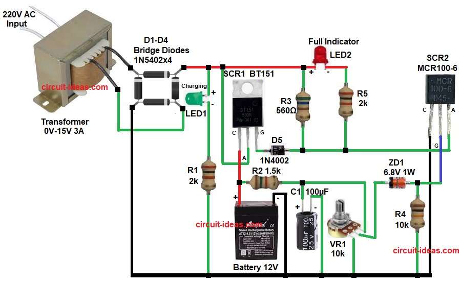
- First, start the circuit by gathering all the components as in diagram above.
- Then start, with transformer primary and connects to 220V AC.
- And transformer secondary gives 15V AC output go to bridge diodes D1-D4 and LED1 and resistor R1.
- After that, start with bridge rectifier D1 to D4 and connect four diodes in bridge form
Output positive goes to SCR1 anode. - Output negative goes to ground.
- SCR1 BT151 anode connects to rectifier positive.
- Cathode connects to battery positive and resistor R2.
- Gate connect to diode D5 cathode.
- SCR2 MCR100-6 anode connect to the junction of resistors R5, R3 and gate of SCR1.
- Cathode connects to ground line of the circuit.
- Gate connects to ZD1 Zener diode anode and resistor R4.
- Zener diode ZD1 cathode connects to middle pin of VR1 pot.
- Anode connects to SCR2 gate and resistor R4.
- Resistor R1 one end is connected in series from cathode of LED and GND.
- R2 one end is connected from cathode of SCR1 and other end is connected to C1 positive and VR1 upper pin.
- R3 one end is connected between SCR1 anode and LED2 anode and other end of R3 is connected between diode D5 anode and resistor R5.
- Lastly, R5 one end is connected between cathode of LED2 and other end of R5 is connected to anode of SCR2.
Conclusion:
This Automatic 12V Battery Charger Circuit with SCR Cutoff gives simple and low cost solution for automatic battery charging.
It uses SCR to control power and stop charging at correct voltage.
Also, it protects battery from overcharge and increases battery life.
Easy construction and less components make this circuit good for beginners and small projects.