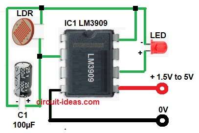
This Automatic Light Control Circuit using LDR and LM3909 IC is small and smart light sensor circuit which can feel light and dark like magic.
It uses few circuit parts like LDR, LM3909 IC, capacitor and an LED.
When dark come, LED turns ON and when light come, LED goes OFF, which is perfect for night lamps or auto lights.
Circuit Working:
Parts List:
| Component | Quantity |
|---|---|
| LDR 1k to 100k | 1 |
| Capacitor | |
| Electrolytic 100µF 25V | 1 |
| Semiconductors | |
| IC LM3909 | 1 |
| LED any color | 1 |
| Battery 1.5V to 5V | 1 |
LDR means Light Dependent Resistor which changes resistance with light, in bright light, LDR resistance is low and in darkness, resistance becomes high.
LM3909 is used as an LED flasher or driver IC and here, it works as a sensor amplifier.
The capacitor C1 helps timing and sensitivity and when light falls on LDR, the resistance drops and this gives lower voltage to the LM3909 input and LED stays OFF.
When it becomes dark, LDR resistance increases and the voltage at input pin of LM3909 also increases, with IC1 activates and LED glows and this is how it senses light and controls LED.
Formula with Calculation:
Below is the formula for Automatic Light Control Circuit using LDR and LM3909 IC:
Resistance of LDR in light is about 1k
Resistance in dark is about 100k
Voltage at input = V = (Rldr / (Rldr + Rother)) × Vcc
If battery is 5V, in dark Vinput = (100k / (100k + 10k)) × 5 = 4.5V
In light Vinput = (1k / (1k + 10k)) × 5 = 0.45V
This voltage difference makes LM3909 switch LED ON or OFF.
How to Build:
To build a Automatic Light Control Circuit using LDR and LM3909 following steps are required to be followed:
- Gather all the parts as shown in circuit diagram.
- Pin 2 of IC1 connect to one end of LDR and positive of capacitor C1.
- Pin 4 connect to battery negative terminal.
- Pin 5 connect to battery positive terminal.
- Pin 6 connect to one anode of LED and cathode of LED connect to negative of capacitor C1
- Pin 8 of IC1 connect to LDR connected in parallel with capacitor C1.
Conclusion:
This Automatic Light Control Circuit using LDR and LM3909 IC is simple and easy to build.
It uses few parts as it works automatically in light and dark and is useful for night lamps, garden lights and small electronic projects.
Leave a Reply