This post is for Broken Cable Detector Circuit using IC CD 4069.
In this circuit there is no need to open wire to check.
It work like metal finder but find AC current in wire but not in metal.
It uses chip CD 4069 and this chip has small switches to turn ON light or buzzer.
If wire is good and has current then it beeps or lights up.
If wire is broken then there will be no beep and no light.
Circuit Working:
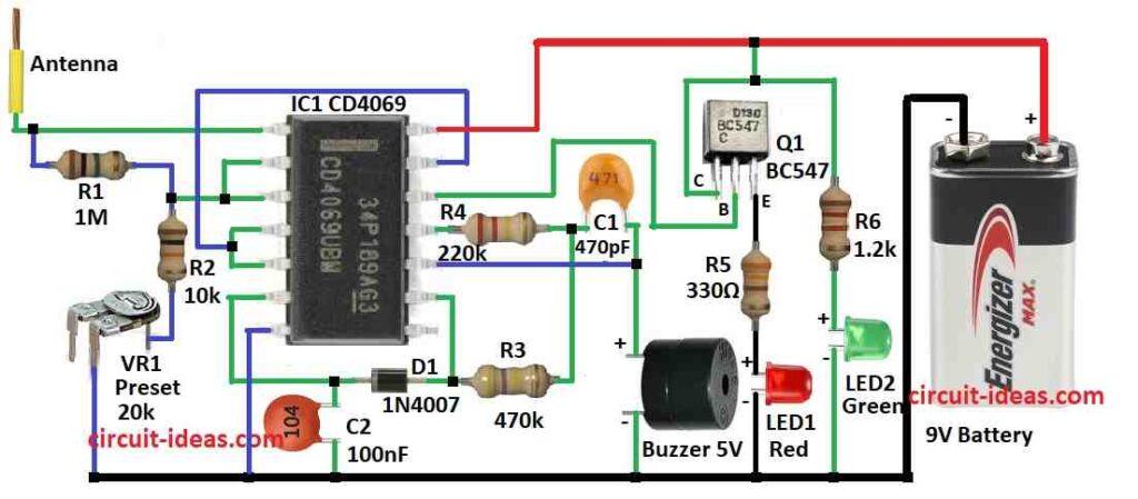
Parts List:
| Component Type | Description | Quantity |
|---|---|---|
| Resistors (All resistors are 1/4 watt unless specified) | ||
| 1M | 1 | |
| 10k | 1 | |
| 220k | 1 | |
| 470k | 1 | |
| 330Ω | 1 | |
| 1.2k | 1 | |
| Preset 20k | 1 | |
| Capacitors | ||
| Ceramic 100nF | 1 | |
| Ceramic 470pF | 1 | |
| Semiconductors | ||
| IC CD 4069 | 1 | |
| Transistor BC547 | 1 | |
| LED Red Green 5mm 20mA | 1 | |
| LED Green 5mm 20mA | 1 | |
| Diode 1N4007 | 1 | |
| Buzzer 5V | 1 | |
| Antenna | 1 | |
| Battery 9V | 1 |
We can make easy broken wire detector using CD 4069 IC.
This chip has six inverters and are used in many circuits.
It can find EMF (electric field) from AC wire but does not show exact broken place.
If wire is cut with no EMF then there is no light or sound.
Parts R3, R4 and C2 make chip work like oscillator and gives signal around 1 kHz.
Transistor Q1 act like switch and is controlled by pin 12 of CD 4069.
LED1 turn ON when EMF is found on wire.
LED2 turn ON when no EMF is found.
Antenna is spiral wire which is about 15 cm long and do not touch live wire.
We can change circuit sensitivity using VR1 which is the variable resistor.
Be careful and always stay safe when checking AC wires.
Never touch live wire with bare hands!
Formulas:
1. LED Resistor RLED:
To stop too much current in LED then use this formula:
RLED = (Vsupply − VLED) / ILED
where,
- Vsupply is the power from battery like 9V
- VLED is the LED voltage drop with around 2V for red/green
- ILED is the LED current for around 20mA
2. Transistor Base Resistor Rbase:
To turn ON transistor fully with saturation, and use this formula:
Rbase = (Vin − Vbe) / Ib
where,
- Vin is the voltage from IC output
- Vbe is the voltage at base-emitter to about 0.7V
- Ib is the base current needed
3. Timing Capacitor C:
If using timer circuit then use this formula:
C = T / (1.1 × R)
where,
- T is the time we want in seconds
- R is the resistor value in ohms
Note:
Exact parts and layout depend on how we want circuit to work.
We may need to test and change some parts to get best result.
Use these formulas to start building and testing our Broken Cable Detector.
Always be safe when working with electricity.
How to Build:
To build a Broken Cable Detector Circuit using IC CD 4069 follow the below mentioned steps for connections
- Collect all parts as shown in circuit diagram.
- Connect pin 1 of CD4069 to antenna.
- Connect pin 2 and pin 3 together.
- From pin 1 connect R1, R2 and VR1 preset in series to ground.
- Connect pin 3 between R1 and R2.
- Connect pin 4 and pin 5 together and also connect them to pin 13.
- Connect pin 6 to pin 11 through C2, D1 and R3 all in series.
- Connect pin 7 to ground.
- Connect pin 9 between D1 and R3.
- Connect pin 10 between C1 and buzzer anode (+ side).
- Connect pin 11 to ground through R4, C1 and 5V buzzer in series.
- Connect pin 12 to base of transistor Q1.
- Connect pin 14 to positive of 9V battery.
Q1 Transistor connections:
- Collector to positive supply.
- Base to pin 12.
- Emitter to ground through R5 and LED1.
- Connect LED2 and R6 between positive and negative lines like a power indicator.
Safety Tips:
- Be very careful with electricity.
- If not sure ask an expert or electrician.
- Never touch live wire with hand.
Conclusion:
This Broken Cable Detector Circuit using IC CD 4069 helps find broken wire without cutting or touching wire.
It does not shows exact broken place but it detects AC field near good wire.
Very useful for quick checking and repair work.
Better to ask help from a certified electrician when working with high voltage.
Leave a Reply