Blinking two LEDs using CD4047 is one of the simplest and most useful beginner electronics projects and this circuit uses the CD4047 IC in astable mode, so it generates a continuous square wave output without any external trigger.
Because of this, the two LEDs blink one after another continuously, in which one LED turns ON while the other turns OFF and then they swap.
This project for CD4047 Astable Multivibrator Circuit for Blinking Two LEDs helps beginners understand oscillator circuits, square wave generation, LED driving, timing circuits and RC frequency control.
Also, this circuit gives a practical idea of how a multivibrator works in real applications like flashers, indicators, clocks and signal generators.
Circuit Working:
Parts List:
| Components | Values | Quantity |
|---|---|---|
| Resistors | 470Ω 1/4 watt | 2 |
| Potentiometer 250k | 1 | |
| Capacitor | Electrolytic 22µF 25V | 1 |
| Semiconductors | IC CD4047 | 1 |
| LED any color | 2 | |
| Battery 9V | 1 |
In this circuit, CD4047 works in astable mode, pins 4, 5, 6 and 14 connect to VDD, so the IC starts free running oscillation.
VR1 and capacitor C1 set the blinking speed, therefore, changing VR1 changes the LED blinking time.
The IC charges and discharges capacitor C1 through VR1 continuously and as a result, the internal oscillator changes its output state.
Pin 10 gives Q output and pin 11 gives Q bar output.
These two outputs work opposite to each other, that means when pin 10 is HIGH then pin 11 becomes LOW.
After half cycle pin 10 becomes LOW and then pin 11 becomes HIGH, because of this LED1 and LED2 blink one by one.
First, LED1 glows through resistor R1 and at the same time LED2 stays OFF and then after half cycle the LED1 turns OFF and LED2 glows through resistor R2.
This process repeats again and again, so both LEDs blink alternately one after another.
How to Build:
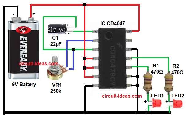
To build a CD4047 Astable Multivibrator Circuit for Blinking Two LEDs follow the below connection steps:
- Start, the circuit first by collecting all the parts as shown in diagram above.
- Next, start with IC pin 1 (C) connect to negative side of capacitor C1.
- Then pin 2 (R) connect to middle terminal of VR1 potentiometer.
- Pin 3 (RC Common) connect to junction point of VR1 lower terminal and positive side of capacitor C1.
- Pin 4 (Astable Input) connect to VDD positive supply.
- Pin 5 (Astable Input) connect to VDD positive supply.
- Pin 6 (-Trigger) connect to VDD positive supply.
- Pin 7 (VSS) connect to battery negative terminal.
- Pin 8 (+Trigger) connect to battery negative.
- Pin 9 (External Reset) also connect to battery negative.
- Pin 10 (Q Output) connect to resistor R1 and LED1 anode and ground.
- Pin 11 (Q Bar Output) connect to resistor R2 and LED2 and ground.
- Pin 12 (Retrigger) connect to ground or battery negative.
- Lastly , pin 14 (VDD) connect to +9V battery positive terminal.
Conclusion:
The CD4047 Astable Multivibrator Circuit for Blinking Two LEDs is a very simple and excellent beginner project, which clearly shows how an astable multivibrator creates continuous pulses.
The complementary outputs at pin 10 and pin 11 make alternate LED blinking very easy.
Also, the potentiometer helps control blinking speed, which makes the circuit more useful for learning and small practical applications like flashers, indicators and signal testing.
This circuit is simple to build, easy to understand and perfect for electronics students and hobby beginners.