First of all, continuity testing is very important in electronics work, as it helps to find broken wires easily and it also helps to check PCB tracks.
Sometimes wires look good but contain internal breaks, so technicians use a continuity tester to check them, hence, this simple Continuity Tester Circuit using an Op-Amp uses an IC 741, a buzzer, and an LED to detect continuity.
When continuity is present the buzzer makes sounds and at the same time the LED glows and therefore, user can hear and see the result easily.
Circuit Working:
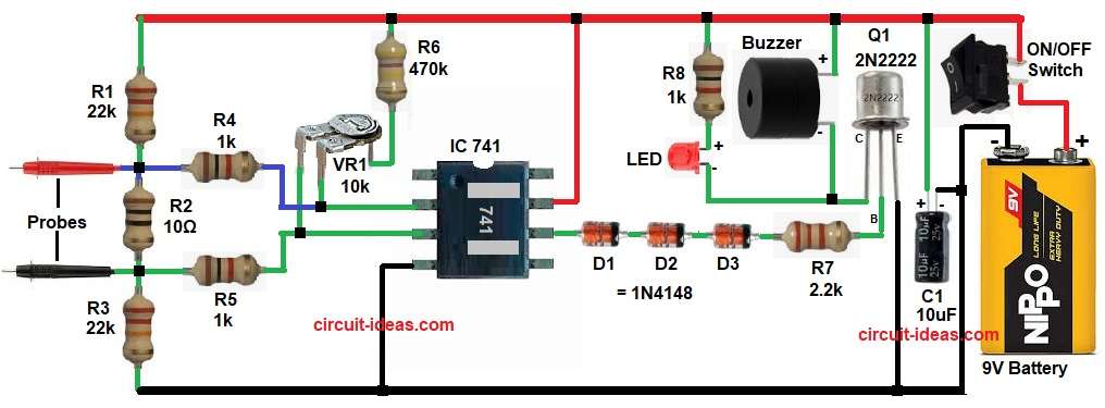
Parts List:
| Components | Values | Quantity |
|---|---|---|
| Resistors | 22k | 2 |
| 10Ω, 470k, 2.2k | 1 each | |
| 1k | 3 | |
| Preset 10k | 1 | |
| Capacitor | Electrolytic 10uF 25V | 1 |
| Semiconductors | IC 741 Op-Amp | 1 |
| Transistor 2N2222 | 1 | |
| LED any color | 1 | |
| Diodes 1N4148 | 3 | |
| 6V to 9V DC Buzzer | 1 | |
| ON/OFF Switch | 1 | |
| 9V Battery | 1 | |
| Probes sharp metal with short flexible wires | 2 |
This circuit works using a voltage comparator principle.
First, connect the probes to the test points and turn ON power switch S1.
When the probes touch a good conductor, current flows and creates a voltage at the op-amp input, then the IC 741 then compares this probe voltage with the reference voltage.
Now, the IC 741 compares this voltage with the reference voltage and if it detects continuity, the IC output goes high.
Next, diodes D1 to D3 conduct and then base current flows to transistor Q1 and after that, transistor turns ON and so the buzzer gets power and sounds.
At the same time, the LED glows to confirm continuity and if the wire breaks, the circuit produces no output voltage.
Hence, op-amp output remains LOW and so transistor stays OFF and thus a buzzer and LED stay OFF.
How to Build:
To build a Continuity Tester Circuit using Op-Amp follow the below steps for connection:
- First, start the circuit by collecting all the parts as shown in circuit diagram.
- Then IC 741 pin 7 connected to positive supply.
- Pin 4 connected to ground.
- Pin 2 is inverting input which connects to VR1 and resistor network.
- Pin 3 is non-inverting input and connects to probe through resistors network.
- Pin 6 is output pin and it connects to diode chain D1 to D3.
- Transistor 2N2222 emitter pin connects to ground, collector pin connected to buzzer and LED and resistor R8 and base pin connected to op-amp output through R7.
- After that, buzzer positive terminal connects to supply and negative terminal connects to Q1 transistor collector pin.
- Finally, power supply 9V battery positive goes to switch S1 and battery negative goes to ground line.
Conclusion:
To conclude, this Continuity Tester Circuit using Op-Amp is simple and reliable and it is easy to build at home as it uses very few components; also it gives both sound and light indication.
Therefore, it is useful for beginners and technicians and it helps in quick fault finding and hence, this circuit is a good practical project.

Leave a Reply