Controlling a DC Motors Direction Circuit with IC 555 Timer is easy to try, as this circuit is good for automation, robotics, devices needing forward and backward move.
Furthermore, circuit has 555 timer, transistor, DPDT relay to change direction and this simple design is easy to build and works in both directions.
Also, 555 timer make astable output to control relay for motor and the whole circuit runs on 12V DC and is easy to use in many systems.
Circuit Working:
Parts List:
| Components | Values | Quantity |
|---|---|---|
| Resistors | 1k 1/4 watt | 1 |
| 10k 1/4 watt | 3 | |
| Potentiometer 100k | 2 | |
| Capacitors | Ceramic 0.01µF | 1 |
| Electrolytic 100µF 25V | 1 | |
| Semiconductors | IC Timer 555 | 1 |
| Transistor BC547 | 1 | |
| Diode 1N4007 | 3 | |
| 12V DPDT Relay | 1 | |
| 12V DC Motor | 1 |
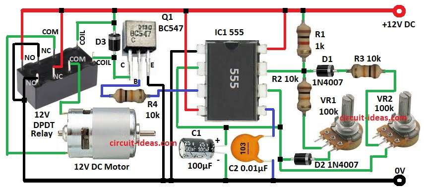
To begin with, circuit uses 555 timer as astable multivibrator to control motor direction and this 555 make pulse output to drive relay.
Then pin 2 (trigger) connect to R3, VR2 and C1 as voltage divider.
When power turns ON, pin 3 outputs a high signal for the time set by the resistor and capacitor, then, transistor Q1 acts as a switch for the relay coil according to the 555 timer signal.
After that, the relay changes the motor polarity and in one position, it cuts power to the motor and in the other position, it supplies power to the motor.
Now D1 & D2 protect 555 from reverse voltage and D3 freewheeling diode protect relay and transistor from spikes.
Also, motor spin direction depend on relay switching.
Formulas:
Formulas for DC motor direction control with 555 timer:
Astable frequency:
f = 1.44 / ((R3 + 2VR2) × C1)
where,
- R3 is 10kΩ
- VR2 is 100kΩ
- C1 is 100µF
How to Build:
For Controlling a DC Motors Direction Circuit with IC 555 Timer follow the below mentioned steps:
- First, gather all parts mentioned in the circuit diagram.
- Next, connect pin 1 of IC1 to GND.
- After that, connect pin 2 of IC1 to pin 6 of IC1.
- Now connect pin 3 of IC1 to the base of transistor Q1 through resistor R4.
- Also, connect pin 4 and pin 8 of IC1 to +12V DC power supply.
- Further, connect pin 5 of IC1 to GND through capacitor C2.
- Connect pin 7 of IC1 between resistor R1 and resistor R2 and connect one end of pot VR1 to resistor R2 and the other end to the cathode of diode D2 and connect the anode of D2 to pin 2 of IC1.
- Next, connect the anode of diode D1 to pin 7 of IC1 and connect the cathode of D1 to one end of resistor R3 and connect the other end of R3 to one end of pot VR2 and connect the other end of VR2 to the anode of diode D2.
- After that, connect the positive terminal of capacitor C1 to pin 2 of IC1 and the negative terminal to GND.
- Now connect the collector of transistor Q1 to the positive supply through diode D3 and connect the emitter of Q1 to GND.
- Also, connect the other coil pin of the 12V relay to the cathode of diode D3 and connect the common poles of the DPDT relay to the motor terminals.
- Finally, connect one NC contact of the DPDT relay to the positive supply and the other NC contact to the negative supply and connect one NO contact of the DPDT relay to the positive supply and the other NO contact to the negative supply.
Conclusion:
To conclude, this Controlling a DC Motors Direction Circuit with IC 555 Timer and relay setup changes motor direction easily and effectively.
Also, the circuit is ideal for automation, conveyors and robots and relay provides electrical isolation for safety and reliability.
Leave a Reply