In my previous post I already made a Simple Voltage Splitter Circuit using uA741 Op-Amp, but this time I added transistors so circuit can handle more current and work more strong.
This DC voltage splitter circuit with op-amp and transistor buffer change single DC supply into dual supply like +V and –V with one virtual ground in center.
Many analog circuits like audio amplifier and op-amp circuit need dual supply, but sometimes only single supply is there, so this circuit solve that problem.
It use op-amp and power transistors to make stable middle voltage point.
Circuit Working:
Parts List:
| Components | Specification | Quantity |
|---|---|---|
| Resistors | 10k | 2 |
| Capacitors | Electrolytic 100µF 25V | 2 |
| IC uA741 Op-Amp | 1 | |
| Transistor TIP41, TIP42 | 1 each | |
| Heatsink for both TIP41, TIP42 | 1 | |
| Diode 1N5402 | 1 |
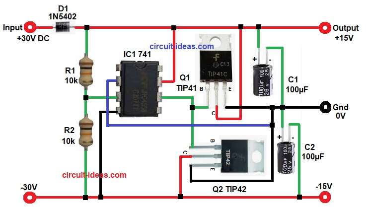
First, the circuit take single DC input and diode D1 protect circuit from reverse polarity.
Next, resistors R1 and R2 divide voltage into half by using formula:
Vref = Vin × (R2 / (R1 + R2))
here,
- Vref is output of voltage divider
- Vin is input voltage
- R1 and R2 are two 10k resistors used to split voltage
Since both resistors are of same value, voltage become 15V and this 15V act like reference and virtual ground.
After that, op-amp compare this reference voltage with feedback and adjust output continuously, so it keep midpoint stable.
Then, op-amp drive TIP41 and TIP42 transistors, and these transistors work like buffer and give current to load.
Because of this, circuit can handle higher current around 250 mA easily, while op-amp only control the working.
Also, capacitors C1 and C2 filter noise and make output more smooth.
Finally, this splitter circuit can take 30V input and give output +15V above ground and –15V below ground.
So, this circuit give stable dual supply from single input with good current capacity.
How to Build:
To build a DC Voltage Splitter Circuit with Op-Amp and Transistor Buffer follow the below connection steps:
- Start, the circuit by collecting all the parts as in diagram above.
- Then start with Op-Amp 741 with pin 2 inverting input connect to midpoint feedback of both the emitter pins of Q1 and Q2 and Gnd.
- Pin 3 is Non-inverting input pin connect between voltage divider R1 and R2 junction.
- Pin 4 negative supply pin so connect to lower rail of 0V.
- Pin 6 output pin connect to transistor Q1 and Q2 base network.
- Pin 7 positive supply pin connect to upper rail.
- Then start with resistor connection with R1 and R2 in series and connect between input positive, pin 3 and -30V.
- Diode D1 connect in series with input positive with anode to input and cathode to circuit.
- Transistor Q1 TIP41 collector pin connect to main positive line.
- Emitter connect to main GND 0V line.
- Base connect to op-amp output of pin 6.
- Transistor Q2 TIP42 collector pin connect to -15V output line.
- Emitter connect to main GND 0V line.
- Base connect to op-amp output of IC pin 6.
- Lastly, capacitors C1 and C2 connect in series between output positive and ground 0V and ground 0V and -15V output line.
Conclusion:
This DC Voltage Splitter Circuit with Op-Amp and Transistor Buffer gives easy way to create dual power supply from single source, as it uses simple components.
It provides stable virtual ground and it works well for low to medium power circuits.
For high current, use bigger transistors and proper heat sink, as this circuit is useful in audio and analog designs where dual supply is needed.
Leave a Reply