In this tutorial, we build a simple diode testing circuit which is very useful for beginners in electronics as it gives good learning and practical use.
Normally, we use a multimeter to test a diode easily but sometimes a normal meter does not test all diode types properly.
For example, a Schottky diode works on high frequency so a normal meter may not check it correctly but this circuit tests it better as it uses IC LM358 op-amp which works on oscillator and generates high-frequency square wave signal.
Also, when we need fast testing this circuit helps to check the diode quickly as it shows if the diode is good or bad and it also shows the diode polarity.
The circuit uses two LEDs for indication and these LEDs clearly show the diode condition.
Moreover, this Diode Tester Circuit using Op-Amp and LED uses a LM358 op-amp and only a few components, so it is very easy to build and therefore, it is a good project for beginners, students and electronics hobby users.
Circuit Working:
Parts List:
| Components | Values | Quantity |
|---|---|---|
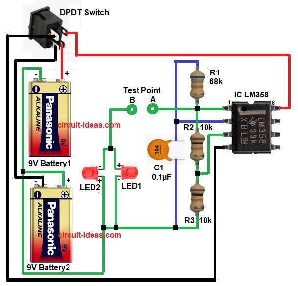
| Resistors | 68k 1/4 watt | 1 |
| 10k 1/4 watt | 2 | |
| Capacitor | Ceramic 0.1µF | 1 |
| Semiconductors | IC LM358 Op-Amp | 1 |
| LEDs any color | 2 | |
| Switch DPDT 4 pin | 1 | |
| Battery 9V | 2 |
In the above circuit , the LM358 IC works as comparator, as it checks the voltage difference and then it gives output according to diode condition.
The resistor network R1, R2 and R3 makes the reference voltage for the IC.
The output comes from pin 1 of LM358 IC and this output goes to test point A and then we connect the diode between point A and point B.
Now, when we connect a good diode in forward direction and current flows through it, so one LED glows and when we reverse the diode the other LED glows but however, if both LEDs glow or if no LED glows then the diode may be short or open.
So by changing the diode direction and watching the LEDs, we can easily test the diode without meter.
The DPDT switch controls dual power lines simultaneously and helps save battery power when the circuit is not in use.
How to Build:
To build a Diode Tester Circuit using Op-Amp and LED follow the below connection steps:
- Start, the circuit by gathering all the circuits parts as in above diagram.
- Next, start with IC LM358 pin 1 which is output pin and connect this pin to test point A and between resistor R1-R2 junction.
- Then take pin 2 which inverting input pin and connect to output pin 1 through resistor R1 and capacitor C1 one side.
- Then take pin 3 which is an non inverting pin and connect between resistor divider middle reference point R2-R3.
- After that, take ground pin 4 and connect to negative supply line or ground 0V.
- Last pin 8 is +Vcc pin and connect to positive of +9V battery1.
- Connect resistor R1 between pin 1 and pin 2 of IC.
- Connect resistor R2 between pin 1 and pin 3 of IC.
- Connect resistor R3 between pin 3 and capacitor C1 one end and LED1 cathode end.
- Connect LED1 and LED2 opposite polarity at point B side.
- Connect two 9V batteries in series for 18V supply.
- Use switch DPDT for ON/OFF supply control as in circuit diagram.
- Finally, connect the diode to be tested between test point A and B.
Conclusion:
This Diode Tester Circuit using Op-Amp and LED is simple, low cost and very useful when a multimeter is not available.
Also the LM358 IC makes the circuit easy to understand for beginners.
Therefore, this project is good for learning basic electronics and practical testing and students can use this circuit in mini projects and lab experiments.