To begin with, a 20W OCL power amplifier circuit gives strong and clear audio output for home speaker systems, computer speakers and small music systems.
Also, this circuit uses TDA2020 audio amplifier IC which can produce good sound quality with low distortion.
Moreover, the circuit needs only few external components, so construction becomes easy for beginners and hobby users.
In this DIY circuit, OCL means Output Capacitor Less design and therefore, speaker directly connects with amplifier output and this method improves sound quality especially in low frequency audio.
Furthermore, the circuit uses a dual power supply from ±12V to ±15V and gives stable audio output through a 4Ω speaker.
Circuit Working:
Parts List:
| Components | Values | Quantity |
|---|---|---|
| Resistors | 3.3k | 1 |
| 100k | 2 | |
| 1Ω | 1 | |
| Capacitors | Ceramic 0.1uF | 4 |
| Ceramic 68pF | 1 | |
| Electrolytic 4.7uF 25V | 1 | |
| Electrolytic 100uF 25V | 2 | |
| Semiconductors | IC TDA2020 | 1 |
| Heatsink for TDA2020 IC | 1 | |
| Diodes 1N4007 | 2 | |
| Speaker 4Ω Speaker | 1 | |
| Power supply ±12V to ±15V | 1 |
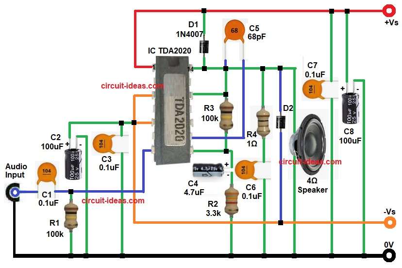
First, audio signal enters through capacitor C1 and this capacitor blocks unwanted DC signal and passes only audio signal into pin 7 of TDA2020 IC.
Then resistor R3 helps input section remain stable and reduces noise problem.
Next, the IC amplifies small audio signal into high power output signal and capacitor C4 and resistor R2 control gain of amplifier and improve frequency response.
Furthermore, resistor R3 provides feedback from output to input section and this feedback helps amplifier produce clear sound with less distortion.
At the output side, resistor R4 and capacitor C6 form Zobel network and this network improves circuit stability and prevents high frequency oscillation.
Moreover, capacitors C2, C3, C7 and C8 filter power supply noise and make amplifier operation smooth.
Diodes D1 and D2 protect the speaker and IC from reverse voltage and unwanted spikes.
Finally, amplified audio signal goes to 4-ohm speaker and speaker produces loud sound output.
Formula with Calculation:
Output Power Formula:
Power = V² / R
where,
- P is power in watts (W)
- V is voltage in volts (V)
- R is resistance in ohms (Ω)
Suppose output voltage = 9V RMS
Speaker resistance = 4 Ohm
Power = 9 × 9 / 4
Power = 81 / 4
Power = 20.25 Watt
Therefore, the amplifier produces nearly 20W output power.
How to Build:
To build a DIY 20W OCL Audio Amplifier Circuit follow the below connection steps:
- Start, the circuit by gathering all the parts as shown in diagram above.
- Then start with IC TDA2020 IC pin 1 goes to +Vs power supply.
- After that, take pin 2 connects with negative supply voltage -Vs.
- Next, pin 5 also connect with pin 3 of IC and then it connects to capacitor C2 and C3 and ground.
- Now pin 7 works as non-inverting input and receives audio signal through C1 and through resistor R1 and ground.
- Then pin 8 works as inverting input and connects with feedback components R2, R3, and C4.
- After that pin 9 connects to pin 14 of IC through capacitor C5.
- Next pin 12 connects to pin 14 of IC and also connects to one end of feedback resistor R3.
- Last pin 14 of IC connects to one end of 4 ohms speaker through diode D1 and resistor R4 and capacitor C6 in series and ground.
- Also, other end of speaker goes to ground of the circuit.
- And also connect diode D2 anode from pin 14 of IC and cathode to -Vs power supply.
- Finally, capacitor C7 and C8 connect from +Vs power supply to ground.
Conclusion:
Overall, this DIY 20W OCL Audio Amplifier Circuit gives good and clear sound with simple circuit design.
Moreover, the circuit uses easily found components and beginners also can build it without much hard work; also, OCL output design gives better sound clarity and stronger bass response.
Finally, proper heatsink and correct power supply help the amplifier work good for long time and also give strong audio output for many sound applications.