In this article How to Interface Microcontroller and Arduino with Relay first we need to think about small computer like Arduino which cannot control big current.
Relay is like one switch and it can handle big current for motor, light and heater.
To connect safe we have used one transistor like translator and one optocoupler like a special isolator.
So small computer can say relay to turn ON or turn OFF even they use different power.
Circuit Working:
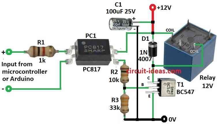
Parts List:
| Type | Value | Quantity |
|---|---|---|
| Resistors (all resistors are 1/4 watt) | 1k | 1 |
| 10k | 1 | |
| 33k | 1 | |
| Capacitors | Electrolytic 100µF 25V | 1 |
| Semiconductors | Optocoupler PC817 | 1 |
| Transistor BC547 | 1 | |
| Diode 1N4007 | 1 | |
| Relay 12V | 1 |
Many time microcontroller use many type of connection together.
Microcontroller (µC) work like this: it read input, do some thinking like processing, and then gives output.
Microcontroller is useful because it can talk to other things like sensor, motor, switch, keypad, display, memory and even other microcontroller.
Sometime we need to connect microcontroller output to one electromagnetic relay (EMR).
Relay is device that let small power control big current or voltage that can turn ON/OFF heavy thing.
Above is one simple circuit to connect microcontroller to relay with galvanic isolation.
Galvanic isolation means two circuit no touch by metal there is no direct wire and no DC current pass between.
This isolation happen by light like optical or coil inductive method.
“Galvanic” mean DC power and so galvanic isolation stop DC from going across.
Most common way is to use optical isolator which is called optocoupler or photocoupler.
One example is PC817 it have small LED inside like infrared and one NPN phototransistor.
This part send signal using light inside but keep input and output safe with no electric connection.
To connect this with microcontroller is easy.
Just connect input side to any output pin of microcontroller.
But be careful about positive and negative polarity.
Whole circuit can run from simple DC power like 12V DC to around 50 mA.
Formulas:
This circuit is easy way to connect microcontroller or Arduino to one relay it uses transistor BC547 to make signal stronger.
Below are some basic electric formulas used:
1. Transistor Base Current (Ib):
This is to check transistor turn ON fully.
Ib = (Vcc – Vbe) / R3
where:
- Ib is current going into transistor base.
- Vcc is supply voltage like 12V.
- Vbe is base emitter voltage which is normally around 0.7V.
- R3 is the resistor at base.
2. Transistor Collector Current (Ic):
This shows if transistor can handle the load.
Ic = hfe × Ib
where:
- Ic is current at transistors collector.
- hfe is gain of transistor from datasheet.
- Ib is base current from above.
3. Relay Coil Current (Ir):
This checks if relay gets enough current.
Ir = Vr / Rcoil
where:
- Ir is current in relay coil.
- Vr is voltage for relay coil that usually is 12V.
- Rcoil is resistance of relay coil from datasheet.
By using this circuit and knowing these simple ideas we can connect microcontroller or Arduino to relay in correct way.
How to Build:
To build a Interface Microcontroller with Relay follow the below mentioned connections steps:
- Connect diode D1 anode to transistor T1 collector.
- Connect D1 cathode to positive power supply.
- Connect transistor emitter (relay driver) to ground.
- Connect transistor base to output pin of PC817 optocoupler through resistors R2 and R3.
- Connect anode of LED inside PC817 to resistor R1.
- Then connect other end of R1 to microcontroller output pin.
- Connect cathode of LED to microcontroller ground.
Important Notes:
- Be sure relay coil voltage is same as the power supply which is 12V in this circuit).
- Use correct transistor and relay and check coil current and ratings.
- Before turning ON the circuit, power check all wires and parts because wrong connection can break things!
Conclusion:
How to Interface Microcontroller and Arduino with Relay is a simple job.
We have used parts like transistor and optocoupler to control high voltage stuff in safe way.
But very important to know relay specs and what microcontroller can give as output.
This help make circuit work right and not damage anything.