A LDR Based Morning Alarm Circuit using NAND Gate IC helps switch on an alarm sound automatically when morning sunlight falls on the sensor.
This circuit uses an LDR (Light Dependent Resistor) and a CD4011 NAND gate IC to detect light and as soon as sunlight reaches the LDR, the resistance of the LDR changes.
Then the CD4011 processes this signal and drives the speaker through transistor stages and therefore, the alarm starts ringing in the morning without manual operation.
This circuit is simple, low cost and useful for morning wake-up alarms, light detection projects and for basic home automation circuits.
Moreover, students and beginners can build this project easily for learning sensor and logic gate applications.
Circuit Working:
Parts List:
| Components | Component | Quantity |
|---|---|---|
| Resistors | 1M, 470k, 22k, 22Ω | 1 each |
| Potentiometer 100k | 1 | |
| LDR 20k to 600k | 1 | |
| Capacitors | Ceramic 0.1µF, 0.001µF | 1 each |
| Electrolytic 100µF 25V | 1 | |
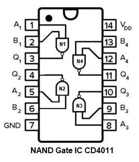
| IC CD4011 Quad NAND Gate | 1 | |
| Transistors BC547, 2N2222 | 1 each | |
| Speaker 8Ω | 1 | |
| SPST On / Off Switch | 1 | |
| 9V Battery | 1 |
At night, when our room is dark the LDR resistance becomes high and because of this the voltage at pin 1 of (N1) gate stays low, so the NAND gate output keeps the speaker OFF.
Then when morning sunlight falls on the LDR, the LDR resistance becomes low and because of this, the input voltage increases.
The first NAND gate gets this changed signal which then sends output to the next gate stages.
After that N2, N3 and N4 gates start working and these stages process the signal and make pulse output.
Also, R1, R2, C1 and C2 make an oscillation signal, so the output changes into tone frequency signal which is not only simple ON signal.
Next, this oscillation signal goes through resistor R3 to transistor Q1 BC547, then this BC547 amplifies the signal and after that, it drives the Q2 2N2222 transistor.
Finally, 2N2222 gives enough current to the speaker, so the speaker produces alarm sound and as sunlight increases more, the circuit works more stable which then keeps alarm sound continuously.
The switch S1 connects and disconnects the 9V battery supply to the circuit.
How to Build:
To build a LDR Based Morning Alarm Circuit using NAND Gate IC follow the below connection steps:
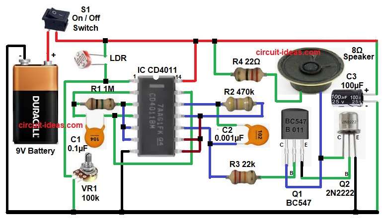
- First, collect all circuit parts as shown in the above diagram.
- Next, connect the LDR from +9V line to pin 1 of IC gate N1.
- Then connect VR1 potentiometer from pin 1 node to ground.
- Now connect pin 2 of IC gate N1 to one end of resistor R1 and capacitor C1.
- Then connect pin 3 of IC gate N1 to one end of resistor R1 and also connect pin 3 to pin 2.
- Then join pin 3 to pin 5 and pin 6 of IC gate N2.
- After that, take pin 4 of IC gate N2 connect it to the other end of capacitor C1 and also connect it to pin 13 of IC gate N3.
- Next, join pin 5 and pin 6 of IC gate N2 together.
- Then connect pin 7 of the IC to circuit ground.
- Now connect pin 14 of the IC to +9V VCC supply.
- Next, take IC gate N3 and connect pin 11 to pin 12 through resistor R2.
- Also join pin 11 with pin 8 and pin 9 of IC gate N4.
- Then connect pin 12 of gate N3 to resistor R2 and one end of capacitor C2.
- Pin 13 of gate N3 connects with pin 4 of gate N2.
- After that, take the last gate N4 and connect pin 8 and pin 9 to pin 11 of gate N3.
- Then connect pin 10 of gate N4 to the other end of capacitor C2.
- Now connect resistor R2 between pin 10 of gate N4 and base of transistor Q1.
- Connect collector of transistor Q1 to one end of the 8 ohm speaker.
- Emitter of transistor Q1 goes to base of transistor Q2.
- Collector of transistor Q2 also connects to one end of the 8 ohm speaker.
- Emitter of transistor Q2 goes to ground.
- Resistor R4 connects from positive line to the other end of the 8 ohm speaker.
- Now connect capacitor C3 positive terminal to +9V line.
- Connect capacitor negative terminal to ground.
- Finally, switch S1 connects and disconnects the 9V battery supply to the circuit.
Conclusion:
This LDR Based Morning Alarm Circuit using NAND Gate IC is a simple and effective automatic light sensing project which detects morning sunlight and immediately activates the speaker alarm.
Also, the circuit uses easily available components and simple logic gate design and therefore, it is an excellent project for beginners, hobbyists and educational use.
Leave a Reply